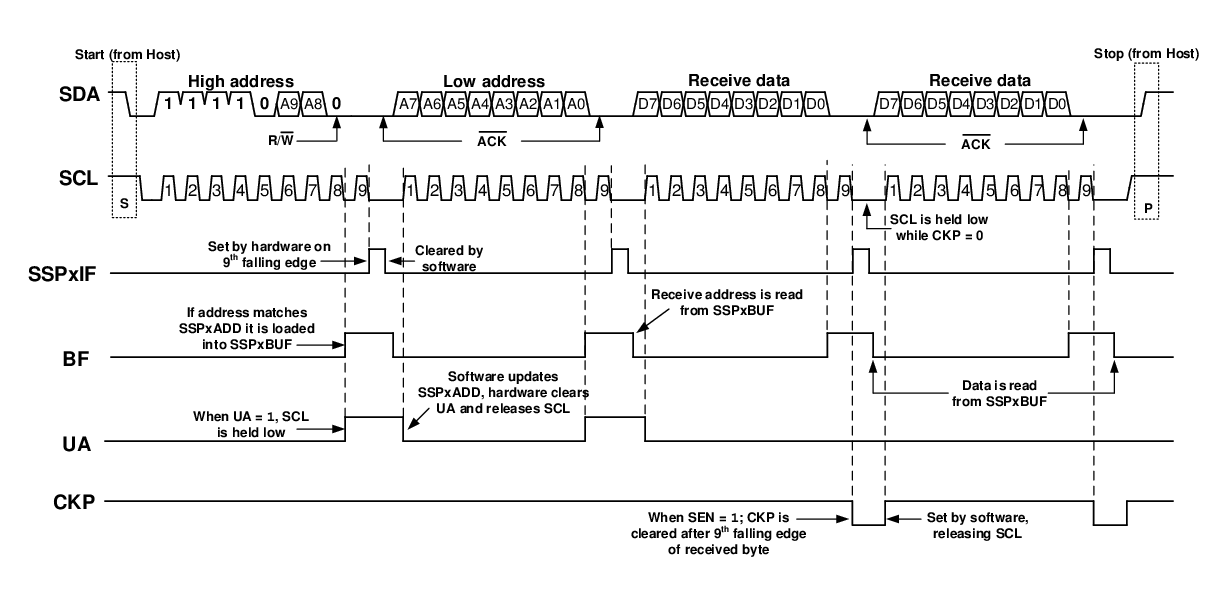
This section describes a standard sequence of events for the MSSP module configured as an I2C client in 10-bit Addressing mode. Figure 1 shows a standard waveform for a client receiver in 10-bit Addressing mode with clock stretching enabled.
This is a step-by-step process of what must be done by the client software to accomplish I2C communication.
- 1.Bus starts Idle.
- 2.Host sends Start condition; S bit is set; SSPxIF is set if SCIE is set.
- 3.Host sends matching high address with the WR/ bit clear; the UA bit is set.
- 4.Client sends ACK and SSPxIF is set.
- 5.Software clears the SSPxIF bit.
- 6.Software reads received address from SSPxBUF, clearing the BF flag.
- 7.Client loads low address into SSPxADD, releasing SCL.
- 8.Host sends matching low address byte to the client; UA bit is
set.Important: Updates to the SSPxADD register are not allowed until after the ACK sequence.
- 9.Client sends ACK
and SSPxIF is set.Important: If the low address does not match, SSPxIF and UA are still set so that the client software can set SSPxADD back to the high address. BF is not set because there is no match. CKP is unaffected.
- 10.Client clears SSPxIF.
- 11.Client reads the received matching address from SSPxBUF, clearing BF.
- 12.Client loads high address into SSPxADD.
- 13.Host clocks a data byte to the client and clocks out the client ACK on the ninth SCL pulse; SSPxIF is set.
- 14.If the SEN bit is set, CKP is cleared by hardware and the clock is stretched.
- 15.Client clears SSPxIF.
- 16.Client reads the received byte from SSPxBUF, clearing BF.
- 17.If SEN is set the client software sets CKP to release the SCL.
- 18.Steps 13-17 repeat for each received byte.
- 19.Host sends Stop to end the transmission.
Figure 1. I2C
Client, 10-Bit Address, Reception (SEN =
1, AHEN = 0,
DHEN = 0)