The PWM module generates a Pulse-Width Modulated signal determined by the duty cycle, period, and resolution that are configured by the following registers:
- T2PR
- T2CON
- PWMxDC
- PWMxCON
Important: The corresponding TRIS bit must be cleared to
enable the PWM output on the PWMx pin.
Each PWM module uses the same timer source, Timer2, to control each module.
Figure 1 shows a simplified block diagram of PWM operation.
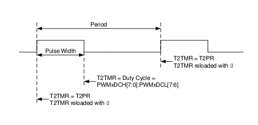
Figure 2 shows a typical waveform of the PWM signal.
Figure 1. Simplified PWM Block Diagram
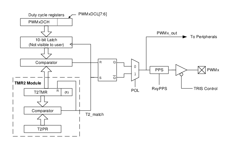
Note:
- 1.8-bit timer is concatenated with two bits generated by FOSC or two bits of the internal prescaler to create 10-bit time base.
Figure 2. PWM Output
For a step-by-step procedure on how to set up this module for PWM operation, refer to Setup for PWM Operation Using PWMx Output Pins.