- 1.The Host generates a Start condition by setting the SEN bit.
- 2.SSPxIF is set by hardware on completion of the Start.
- 3.SSPxIF is cleared by software.
- 4.Software writes SSPxBUF with the client address to transmit and the R/W bit set.
- 5.Address is shifted out the SDA pin until all eight bits are transmitted. Transmission begins as soon as SSPxBUF is written to.
- 6.The MSSP module shifts in the ACK value from the client device and writes it into the ACKSTAT bit.
- 7.The MSSP module generates an interrupt at the end of the ninth clock cycle by setting the SSPxIF bit.
- 8.Software sets the RCEN bit and the host clocks in a byte from the client.
- 9.After the eighth falling edge of SCL, SSPxIF and BF are set.
- 10.Host clears SSPxIF and reads the received byte from SSPxBUF, which clears BF.
- 11.Host clears the ACKDT bit and initiates the ACK sequence by setting the ACKEN bit.
- 12.Host’s ACK is clocked out to the client and SSPxIF is set.
- 13.User clears SSPxIF.
- 14.Steps 8-13 are repeated for each received byte from the client.
- 15.Host sends a NACK or Stop to end communication.
Figure 1. I2C
Host Mode Waveform (Reception, 7-Bit Address)
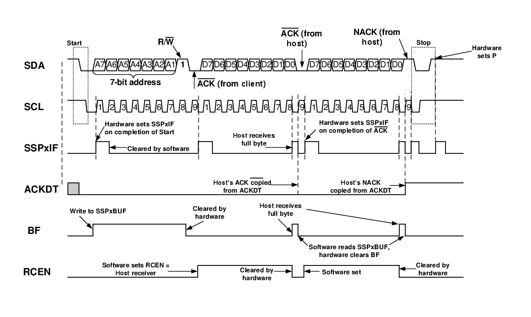
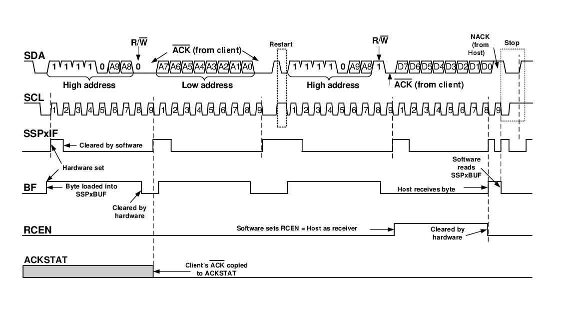
Figure 2. I2C Host Mode Waveform
(Reception, 10-Bit Address)