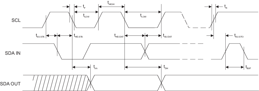
Figure 1. I2C Synchronous Data Timing
| Parameter | Sym. | Min. | Max. | Units |
|---|---|---|---|---|
| SCL Clock Frequency | fSCL | 0 | 1 | MHz |
| SCL High Time | tHIGH | 400 | — | ns |
| SCL Low Time | tLOW | 400 | — | ns |
| Start Setup Time | tSU.STA | 250 | — | ns |
| Start Hold Time | tHD.STA | 250 | — | ns |
| Stop Setup Time | tSU.STO | 250 | — | ns |
| Data In Setup Time | tSU.DAT | 100 | — | ns |
| Data In Hold Time | tHD.DAT | 0 | — | ns |
| Input Rise Time1 | tR | — | 300 | ns |
| Input Fall Time1 | tF | — | 100 | ns |
| Clock Low to Data Out Valid | tAA | 50 | 550 | ns |
| Data Out Hold Time | tDH | 50 | — | ns |
| SMBus Time-Out Delay | tTIMEOUT | 25 | 75 | ms |
| Time bus must be free before a new transmission can start1 | tBUF | 500 | — | ns |
Notes:
- 1.Values are based on characterization and are not tested.
- 2.AC measurement conditions:
- RL (connects between SDA and VCC): 1.2 kΩ (for VCC = +2.0V to +5.0V)
- Input pulse voltages: 0.3VCC to 0.7VCC
- Input rise and fall times: ≤ 50 ns
- Input and output timing reference voltage: 0.5VCC