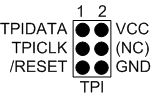
When designing an application PCB, which includes an AVR with the TPI interface, the pinout shown in the figure below, should be used.
Figure 1. TPI Header Pinout
| AVR PORT Pins | Target Pins | TPI Pinout |
|---|---|---|
| Pin 1 (TCK) | CLOCK | 3 |
| Pin 2 (GND) | GND | 6 |
| Pin 3 (TDO) | DATA | 1 |
| Pin 4 (VTG) | VTG | 2 |
| Pin 5 (TMS) | ||
| Pin 6 (nSRST) | /RESET | 5 |
| Pin 7 (not connected) | ||
| Pin 8 (nTRST) | ||
| Pin 9 (TDI) | ||
| Pin 10 (GND) |