The figure below shows the interconnections of the MPLAB ICE 4 In-Circuit Emulator to the connector on the target board. The diagram also shows the wiring from the connector to a device on the target PCB. A pull-up resistor Rpu, usually around 10 kΩ, connected from the VPP/MCLR line to the VDD is recommended so that the line may be strobed low to reset the device.
Figure 1. ICSP Connection Target
Circuitry
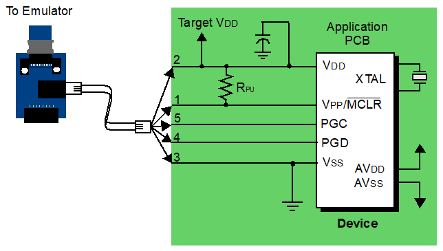
| Pin No. | Device I/O | Description |
|---|---|---|
| 1 | Vpp/MCLR | The emulator requires access to Vpp for programming and debugging the device. |
| 2 | Vdd | Target Vdd is sensed by the emulator to allow level translation for target low-voltage operation and to detect a device. If the emulator does not sense voltage on its Vdd line, it will not connect with the device. |
| 3 | Vss | Target Vss is sensed by the emulator. Note: The emulator DOES NOT
provide target Vss or ground.
|
| 4 | PGD | The emulator requires access to PGD and PGC for programming and debugging the device. |
| 5 | PGC |
| Device I/O | Description |
|---|---|
| Vpp/nMCLR and Vdd | A pull-up resistor (10kΩ typical) should be connected from the Vpp/MCLR line to Vdd so that the line may be strobed low to reset the device. |
| XTAL | The target device must be running with an oscillator for the emulator to function as a debugger. |
| AVdd, AVss | Not all devices have the AVdd and AVss lines, but if they are present on the target device, all must be connected to the appropriate levels in order for the emulator to operate. This also applies to voltage regulator pins (e.g., ENVREG/DISVREG on PIC24FJ MCUs). |
| Vdd, Vss, AVdd, AVss | In general, it is recommended per device data sheet that all Vdd/AVdd and Vss/AVss lines be connected to the appropriate levels. For devices with a Vcap pin (e.g., PIC18FXXJ devices), the appropriately-valued capacitor should be placed as close to the Vcap pin as possible. |