The two current measurement channels of the Power Debugger are useful when analyzing current consumption of two different domains. For example, both board-level current draw and MCU-only current draw can be plotted.
To best demonstrate a USB hardware device, we will make use of a Mass Storage Device example from ASF.
Todo:
- In Atmel Studio, create a New Example Project
- In the New Example dialog, select the SAM L21 device family (or other relevant device) and filter by the keyword “MSC”
- Select the USB Device MSC Example
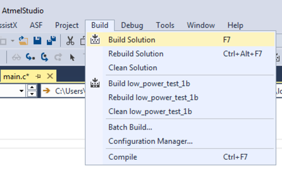
- Build the project/solution (F7)
Todo:
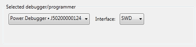
- Open the project properties (right click the project in the Solution Explorer and select Properties)
- On the Tool tab, select the appropriate tool and interface
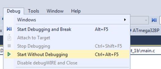
Todo: Program the application into the target device using Start Without Debugging
(Ctrl+Alt+F5).
Info: In
this part of this example we are going to make use of the Programming mode only. In
most systems running code through a debugger will not yield accurate current
measurements. This is because the target device’s debug module (OCD) requires a
clock source which cannot be disabled while debugging.