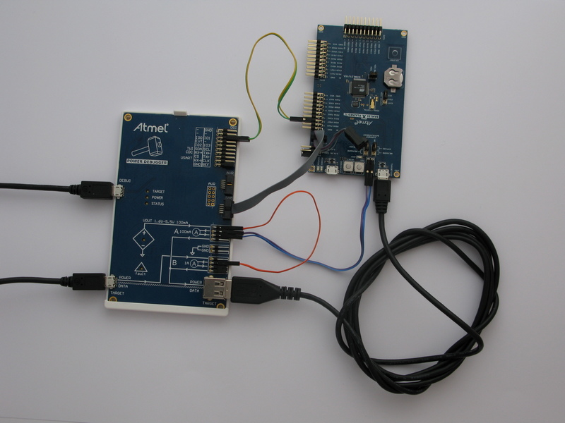
Connect the kits according to the block diagram. Connections are described here:
To power the target: We will power the target from the variable voltage supply. This enables testing a USB device over the full voltage range of the USB specification.
- Connect the variable voltage output to the input of the B channel using a strap cable. This enables us to measure the total current drawn by the target.
- Connect the output of the B channel to the POWER input of the USB type-A jack. This is simply done by using a jumper.
- Connect a USB cable from the type-A jack to the TARGET USB micro-jack
To measure the current drawn by the target MCU: the Xplained PRO board has a power 2-pin header next to the TARGET USB connector. Usually a jumper is in place here connecting VCC_TARGET to VCC_MCU. By removing this jumper and routing this circuit through a current measurement channel we can measure the current drawn only by the MCU, and not the whole board.
- Connect VCC_TARGET on the target board to the input of the A channel
- Connect the output of the A channel to the VCC_MCU pin of the target board
To make use of GPIO instrumentation: The Power Debugger has four GPIO channels, which can be monitored in Data Visualizer. We can then add pin toggles into the application code and view these events in Data Visualizer.
- Connect PB07 (GPIO0) on the Xplained PRO EXT1 header to IO0 on the DGI header on the Power Debugger
- Connect PB06 (GPIO1) on the Xplained PRO EXT1 header to IO1 on the DGI header on the Power Debugger
To program and debug the target device: Although the Xplained PRO has debug capability, we will use the Power Debugger for this purpose.
- Connect the 10-pin debug cable from the SAM header of the Power Debugger to the CORTEX DEBUG header of the Xplained PRO
To connect all this to the host computer:
- Connect a USB cable from the DEBUG connector of the Power Debugger to the host computer
- Connect a USB cable from the TARGET connector of the Power Debugger to the host computer