Pin toggling is often a simple and useful mechanism for debugging applications. We will now add some simple instrumentation to profile the read and write cycles of the Mass Storage device.
Add instrumentation as shown here, which toggles GPIO0 for read accesses and GPIO1 for write accesses:
voidui_start_read(void){// GPIO0 high
    port_pin_set_output_level (EXT1_PIN_GPIO_0, true);}voidui_stop_read(void){// GPIO0 low
    port_pin_set_output_level (EXT1_PIN_GPIO_0, false);}voidui_start_write(void){// GPIO1 high
    port_pin_set_output_level (EXT1_PIN_GPIO_1, true);}voidui_stop_write(void){// GPIO1 low
    port_pin_set_output_level (EXT1_PIN_GPIO_1, false);}
Find the board_init.c file and add initialization of GPIO0 and 1. This can be added by copying the LED_0_PIN initialization in system_board_init (void)
// GPIO0 to outputport_pin_set_config(EXT1_PIN_GPIO_0,&pin_conf);// GPIO1 to outputport_pin_set_config(EXT1_PIN_GPIO_1,&pin_conf);voidui_process(uint16_t framenumber){/*if (0 == framenumber) {
LED_On(LED_0_PIN);
}
if (1000 == framenumber) {
LED_Off(LED_0_PIN);
}*/}- Build the project/solution (F7)
- Program the application into the target device using Start Without Debugging (Ctrl + Alt + F5)
- Switch to Data Visualizer to see the results
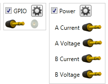
- Select both the Power interface and GPIO and start visualizing
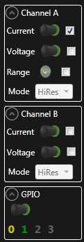
- Open the control panel
- Uncheck channel B
- Uncheck GPIO 2 and 3
The power graph should now look similar to the previous exercise. Now perform a disk format through Windows, and note how the GPIO 0 and 1 signals toggle. Stop the visualizer or disable auto-scrolling and zoom in to an interesting bit. One can clearly see how each read and write access has a GPIO toggle to indicate a Start and Stop condition.
- Create a new text file
- Add content using notepad
- Save the file
- Re-open the file
- Delete the file