Again, our power consumption has been reduced but the CPU is still in a “lighter” Sleep mode than it needs to be. To go into Power-Down mode we have to switch to the Watchdog Timer as a wake-up source. When the watchdog wakes and triggers an interrupt, we light the LED and go into IDLE mode until we switch it off again. The code below is included in project low_power_104.
#include<avr/io.h>#include<avr/interrupt.h>#include<avr/sleep.h>#include<avr/power.h>#include<avr/wdt.h>volatile uint8_t deep_sleep =0;

ISR (WDT_vect){// LED is OFF, turn it on
    PORTB =(1<<5);// Flag a lighter sleep state
    deep_sleep =0;}

ISR (TIMER2_OVF_vect){// LED is ON, turn it off
    PORTB =0x00;// Flag a deep-sleep state
    deep_sleep =1;}intmain(void){// Disable digital input buffer on ADC pins
    DIDR0 =(1<< ADC5D)|(1<< ADC4D)|(1<< ADC3D)|(1<< ADC2D)|(1<< ADC1D)|(1<< ADC0D);// Disable digital input buffer on Analog comparator pins
    DIDR1 |=(1<< AIN1D)|(1<< AIN0D);// Disable Analog Comparator interrupt
    ACSR &=~(1<< ACIE);// Disable Analog Comparator
    ACSR |=(1<< ACD);// Disable unused peripherals to save power// Disable ADC (ADC must be disabled before shutdown)
    ADCSRA &=~(1<< ADEN);// Shut down the ADCpower_adc_disable();// Disable SPI power_spi_disable();// Disable TWIpower_twi_disable();// Disable the USART 0 modulepower_usart0_disable();// Disable the Timer 1 modulepower_timer1_disable();// Disable the Timer 0 and 2 modulespower_timer0_disable();// Timer 2 needs to stay on//power_timer2_disable();// Change the clock prescaler
    CLKPR =(1<< CLKPCE);// Scale by DIV64
    CLKPR =(1<< CLKPS2)|(1<< CLKPS1)|(0<< CLKPS0);// Port B5 to output
    DDRB =(1<<5);// Watchdog resetwdt_reset();// Start timed sequence
    WDTCSR |=(1<<WDCE)|(1<<WDE);// Set new prescaler(time-out) value = 64K cycles (~0.5s)
    WDTCSR =(1<<WDIE)|(1<<WDP2)|(1<<WDP1);// Timer2 DIV 32
    TCCR2B =(0<< CS22)|(1<< CS21)|(1<< CS20);// Overflow interrupt enable
    TIMSK2 =(1<< TOIE2);// Interrupts onsei();while(1){// If deep sleep, then power downif(deep_sleep)set_sleep_mode(SLEEP_MODE_PWR_DOWN);else{// Shorter sleep in idle with LED on
TCNT2 =0;set_sleep_mode(SLEEP_MODE_IDLE);}sleep_mode();}}- Build the project/solution (F7)
- Program the application into the target device using Start Without Debugging (Ctrl+Alt+F5)
- Switch to Data Visualizer to see the results
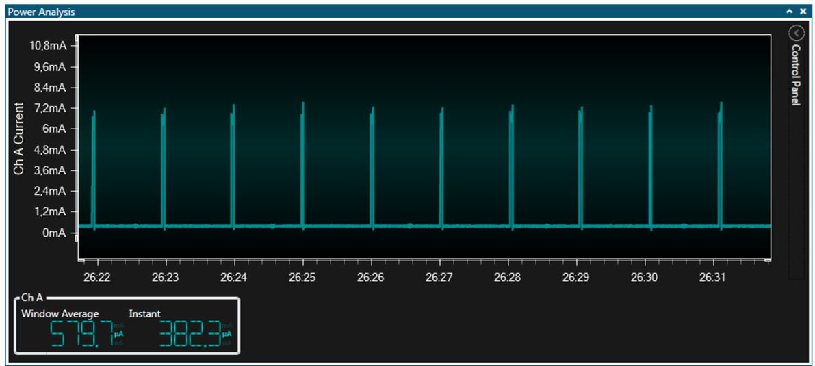
- Even lower power consumption with the LED OFF
Now let’s take a brief and closer look at the details of our plots. Enabling cursors allows us to take more accurate measurements from the plot.
- Open the Control Panel in the upper right corner of the Power Analysis module
- Expand the Cursors section
- Click the Enabled box to turn the cursors on
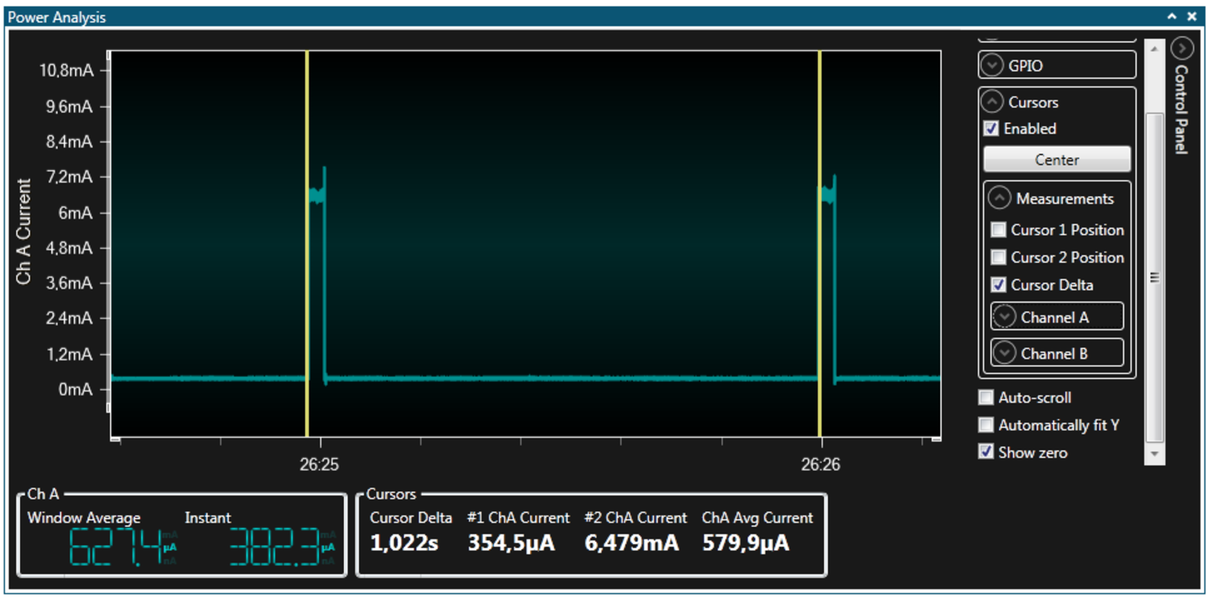
In the plot above we use two cursors to first check the delta - confirming that the Watchdog Timer interrupts approximately every second, as expected.
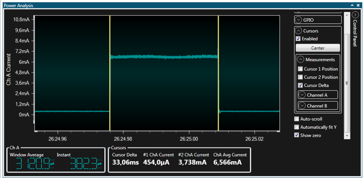
Zooming further in we can see that the width of the ‘on’ pulse (shown as Cursor Delta) is a little over 33 ms. This equates to a duty-cycle of 3.3% - a touch higher than intended (1%). The main clock is 16 MHz at 5V, and we are using DIV64 CLKPR, and DIV32 on TIMER2, giving it a 128 μs tick. With overflow every 256 cycles the LED on period is thus 32.7 ms, close to our measurement. So to achieve a 1% duty-cycle TIMER2 preload value can be increased from 0x00 to 0xB2.
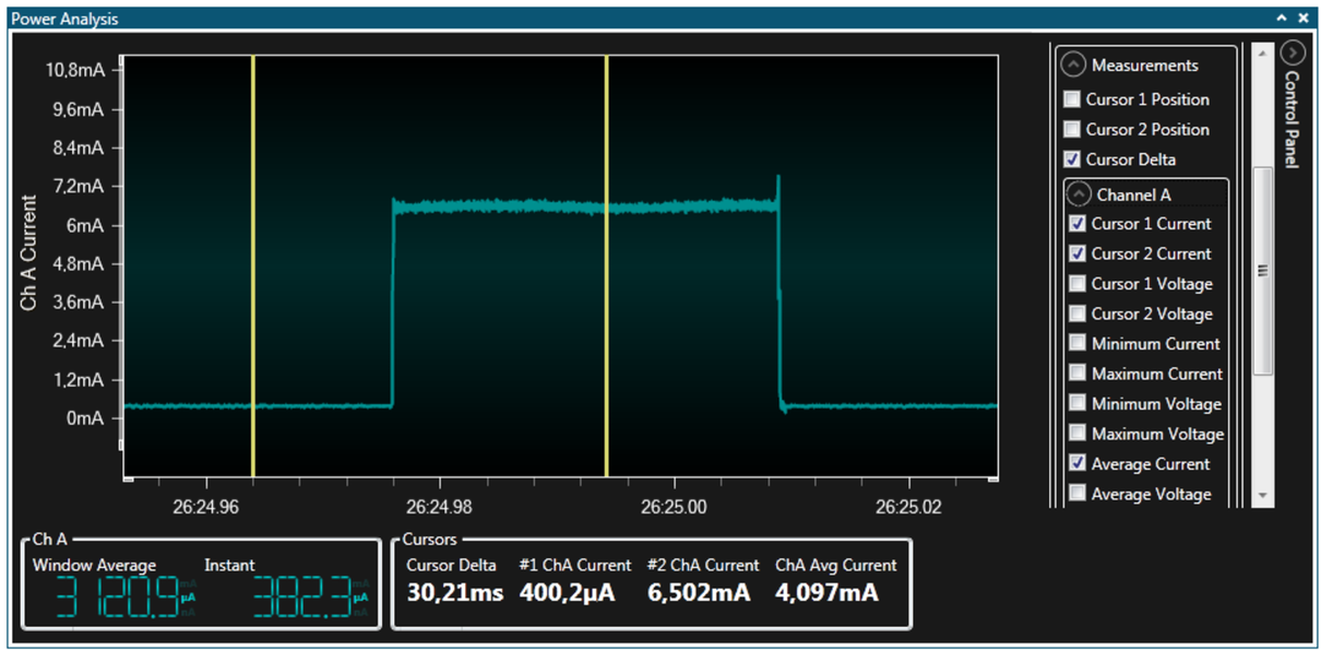
To get more accurate current measurements from the plots, enable the cursor current measurements as shown here. The cursor values are shown as about 400 μA with the LED OFF and 6.5 mA with the LED ON.