Once the hardware modifications have been made we are ready to connect the Power Debugger to the target.
To measure the current on the ATmega328PB device you will have to route its supply through the Power Debugger. With the FET switch set to OFF, the ATmega328PB device has no target power source. To route the 5V Xplained Mini supply voltage through the A channel and into the ATmega328PB device’s supply rail:
Todo:
- Connect the 5V pin on the power-header of the Xplained Mini board to the input pin of the A channel on the Power Debugger
- Connect the output pin of the A channel to the VCC pin of the power header on the Xplained Mini
Connect the USB and programming cables:
Todo:
- Connect the debug cable from the AVR output of the Power Debugger to the ISP header of the Xplained Mini board
- Plug both Power Debugger and Xplained Mini into USB ports on the host computer
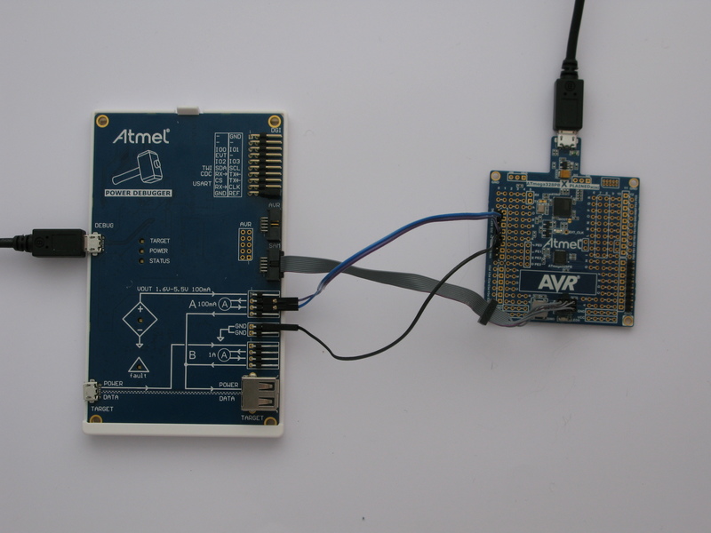
Your setup should look something like this:
If the debugWIRE interface on the target device is enabled, it will need to be disabled.
Tip: If you are able to read the device signature using ISP after a power
toggle, then debugWIRE is successfully disabled and DWEN is cleared.