The Power Debugger contains a USB “feed-through” section across its lower side. This is a convenience feature enabling a quick and easy connection to USB powered target boards.
The USB feed-through section has two USB connectors:
- The left side “TARGET” connector is a USB Micro-B jack. Connect this to the host computer using the cable included in the kit.
- The right side “TARGET” connector is a USB Type A jack. Connect this to the board being debugged.
Figure 1. USB Feed Through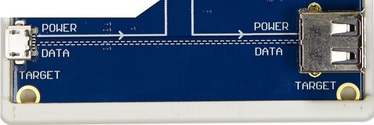
The routing of the USB feed-through section is clearly indicated by the silkscreen on the
board:
- DATA lines are passed through untouched from the Micro-B jack to the A jack
- GND is connected to the board ground
- SHIELD is connected to board ground through a 1MΩ resistor
- POWER (VBUS) is routed from the Micro-B jack to pin 1 on the B channel header
- POWER (VBUS) is routed from pin 4 on both A and B channel headers to the A jack
The routing of the POWER line enables the user to easily connect up one of the following configurations:
- Routing USB power from the TARGET USB
connector through the B channel for measurement.
Mount both jumpers on the B channel header as shown here.
Figure 2. Jumper Configuration
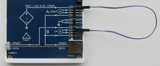
- Routing USB power from the TARGET USB
connector through the A channel for measurement
Use a single wire to connect POWER to the A channel and a jumper to connect the output as shown here.
Figure 3. Jumper Configuration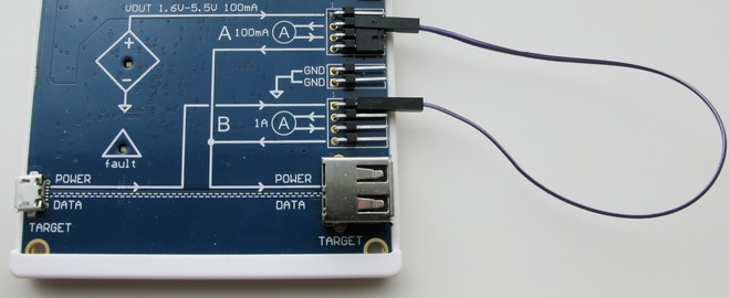
- Sourcing USB power from the DEBUG USB
connector through the variable voltage source through the A channel
Mount both jumpers on the A channel as shown here.
Figure 4. Jumper Configuration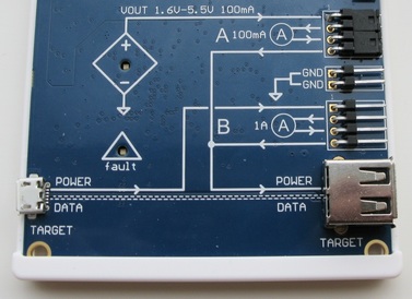
- Sourcing USB power from the DEBUG USB connector through the variable voltage source
through the B channel
Use a single wire to connect POWER to the B channel and a jumper to connect the output as shown here.