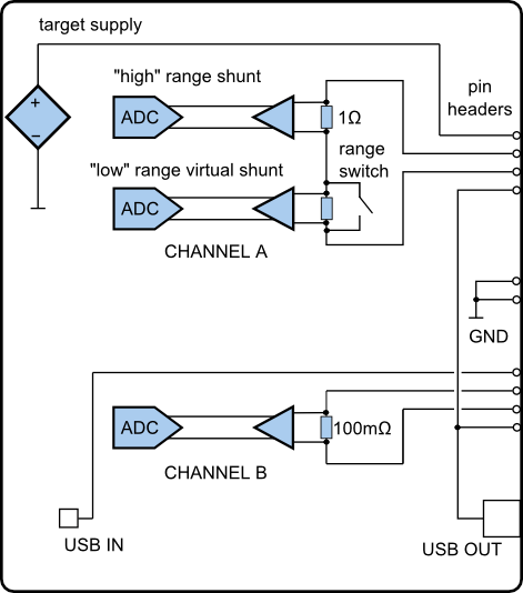
The Power Debugger analog front-end contains two channels, referred to as the ‘A’ channel and the ‘B’ channel. Although they operate on similar mechanisms, the two channels are not symmetrical and should be used for different purposes.
Both channels are fed into independent ADC channels on the AVR XMEGA128A1U microcontroller. This ADC module allows for the ‘A’ channel to operate totally independently at maximum sampling rate while the ‘B’ channel ADC is shared with both channels’ voltage measurement, which are sampled less frequently.
The ‘A’ channel is the recommended channel for accurately measuring low currents. It features two shunt stages, which through bypass switches, provide a circuit capable of measuring from 100 mA on the top-end down to under 1 μA. Range switching is done automatically, and it is possible to lock sampling into the high-range only should this be needed.
- 1.‘A’ channel high range: 100 mA - 500 μA, ~3 μA resolution.
- 2.‘A’ channel low-range: 1 mA - 1 μA, ~30 nA resolution.
The sampling rate of the ‘A’ channel is 62.5 kHz and data is sent in 16-bit frames to the host computer. A calibrated ‘A’ channel has accuracy no worse than 3% down to around 1 μA.
The ‘B’ channel is the recommended channel for measuring higher currents with lower resolution than the ‘A’ channel. It is based on a single shunt resistor allowing measurement of current up to 1A and down to 1 mA.
- 1.‘B’ channel single range: 1A, ~500 μA resolution.
Data is sampled at 62.5 kHz and transferred to the computer in 12-bit frames.