Unipolar switching requires two transistors to be energized during one trapezoidal step.
The low-side transistor is conducting all the time, while the upper one is receiving a PWM signal. In most applications, the high-side transistor command is handled by a MOSFET driver. The MOSFET driver has a bootstrap capacitor that charges when the low side is conducting. If the method used applies the PWM on the low side, the bootstrap capacitor will be charged depending on the duty cycle, resulting in a low charge at a low percentage of the duty cycle, which will result in an increase of the RDS (on) of the transistors and will decrease the overall efficiency, or under-voltage lock-out of the driver IC chip.
In sensorless control, this method poses a few challenges:
- During the time in which the BEMF is
exposed, the waveform will be chopped due to magnetic coupling between all of the
coils, as the PWM is induced in the floating phase.
Thus, a synchronizing method is needed to ‘sample’ the BEMF at specific times. This sampling time is ideally at the middle of a high pulse, where the BEMF stabilizes and does not vary.
- Any noise that overlays the waveform
will be hard to filter and will trigger the zero-cross at the wrong time, which will
decrease the efficiency and increase both acoustic and electrical noise.
In this method, the traditional RC filter method will prove inefficient at low speeds as it will require high values and introduce a high amount of delay at high speeds.
A typical waveform using unipolar switching can be seen in Figure 1.
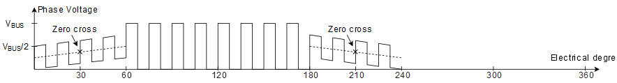
This is a classic scenario used in most simple designs.