It may be that the motor fails to start, or it does not exhibit good performance.
The following paragraphs will focus on the tuning parameters and their impact on the system behavior:
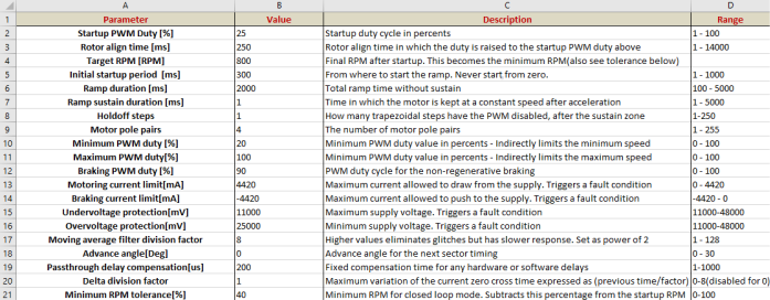
- 1. Start-up PWM Duty [%] – It
represents the start-up duty cycle in percentage. A value that is too low may be
insufficient for the ramp-up sequence as the current through the windings is too low
and the generated magnetic field is not strong enough for the rotor to follow.
A value that is too high will result in a trigger of the overcurrent protection or excessive heating of the windings. The start-up duty cycle is also strongly dependent on the motor load at start-up. Higher loads demand higher duty cycles.
This parameter applies to the ramp-up sequence only.
- 2.Rotor align time [ms] – The
rotor align time in milliseconds. The duty cycle is gradually increased using a
linear ramp from 0% to the Start-up PWM Duty value so there is no mechanical shock.
This alignment is done for the motor to start from a known position.
This parameter applies to the ramp-up sequence only.
- 3.Target RPM [RPM] – This will
be the final RPM after the ramp-up sequence. If it is set too high, then there will
be a need for a higher duty cycle so that the motor can follow the magnetic field at
high RPMs.
This parameter applies to the ramp-up sequence only, but the closed-loop control also depends on it.
- 4.Initial start-up period [ms] –
Start-up point of the ramp. There is generally no need to tune this parameter.
This parameter applies to the ramp-up sequence only.
- 5.Ramp duration [ms] – Sets how
much the ramp will last. For faster start-up times, lower this value. Beware that
strong accelerations also demand higher duty cycles.
This parameter applies to the ramp-up sequence only.
- 6.Ramp sustain duration [ms] –
After the ramp-up sequence, where the motor is accelerated, there is a sustained
period where the motor is spun with the Target RPM speed. Unless there is a
PI controller used, where it can benefit in the training of the controller, it is
recommended for this parameter to be kept to a minimum.
This parameter applies to the ramp-up sequence only.
- 7.Hold-off steps – Immediately
after the ramp-up sequence, the PWM is disabled and the comparator is enabled. This
is done to detect the exact position of the rotor in absence of any phase noise.
This parameter needs to be kept to a minimum of one unless there is a very slow
variation of the phase voltage of the motor.
This parameter applies to the ramp-up sequence only.
- 8.Motor pole pairs – The number of pole pairs of the motor.
- 9.Minimum PWM duty [%] – The
minimum PWM duty cycle. Use this parameter to limit the minimum speed of the
motor.
This parameter applies to the closed and open-loop control.
- 10.Maximum PWM duty [%] – The
maximum PWM duty cycle. Use this parameter to limit the maximum speed of the
motor.
This parameter applies to the closed and open-loop control.
- 11.Braking PWM duty [%] – The
duty cycle for the motor in Stop mode. The system is protected from overcurrents
caused by braking at high speeds. In this case, the firmware will get to the Fault
state and protect the transistors.
This parameter applies to the Stop state only.
- 12.Motoring current limit [mA] –
The maximum current value that can be drawn from the bus over which the Fault
condition is triggered. The maximum value is limited by MCLV-2 to 4420 mA.
This parameter applies to all system states except for the Error Handling state.
- 13.Braking current limit [mA] –
The maximum current value that can be pushed to the bus over which the Fault
condition is triggered. The maximum value is limited by MCLV-2 to -4420 mA.
This parameter applies to all system states except for the Error Handling state.
- 14.Undervoltage protection [mV] –
The minimum voltage on the bus for the MCLV-2. Do not set under 11V.
This parameter applies to all system states except for the Error Handling state.
- 15.Overvoltage protection [mV] –
The maximum voltage for the system. Do not set over 24V if using a single supply, or
over 48V if using dual supplies (see the MCLV-2 user guide).
This parameter applies to all system states except for the Error Handling state.
- 16.Moving average filter division factor – The division factor for the moving average filter of the zero-cross time needs to be set as a power of two because it can be optimized by the compiler with right shifts. Higher values are recommended because the system has higher immunity to any glitches but limits the maximum variation between 2 zero-cross events, thus limiting the maximum acceleration of the motor. This parameter applies to the closed-loop control only.
- 17.Advance angle [Deg] – The
advance angle of the motor. Increasing this value will advance the generation of the
waveforms with that specific degrees, concerning the motor back-EMF zero-cross
point. Also, it will have an impact on the torque generated by the motor.
This parameter applies to the closed-loop control only.
- 18.Pass-through delay compensation
[us] – Fixed advance time for the next sector timing. This value is directly
subtracted from the next sector timing to compensate for any software or hardware
delays.
This parameter applies to the closed-loop control only.
- 19.Delta division factor – This
parameter controls an additional stall and glitch detection mechanism. In the case
of very early or very late detection of the zero-cross point, if the absolute
difference between the previous zero-cross time and the currently measured time is
more than the previous zero-cross time/Delta division factor, then a Fault condition
is triggered. The Delta division factor is ideal to be chosen as a power of two for
code efficiency. A value too high will make the system very unstable and will limit
the maximum acceleration by triggering the Fault condition. A value too low may not
detect a glitch very well but will not encounter any troubles at start-up.
This parameter applies to closed-loop control only.
- 20.Minimum RPM tolerance [%] –
This parameter controls the time-out and the minimum RPM for the timer. After the
start-up, it may be that the system will detect the zero-cross point a bit later
than it needs to, and if the tolerance is very low, it will be considered as a
time-out event. To avoid that, a given tolerance is needed under the shape of a
percentage of the minimum RPM. The minimum RPM thus becomes Target RPM -
Target RPM * Minimum RPM tolerance.
This parameter applies to the closed-loop control only.
After modifying the parameters, press the Patch File button, then recompile and program the AVR DX with the firmware.