The System State Machine
The firmware is based on a state machine that controls how the system behaves. It provides Fault handling, Reset information, and enables debugging by utilizing error messages transmitted via UART.
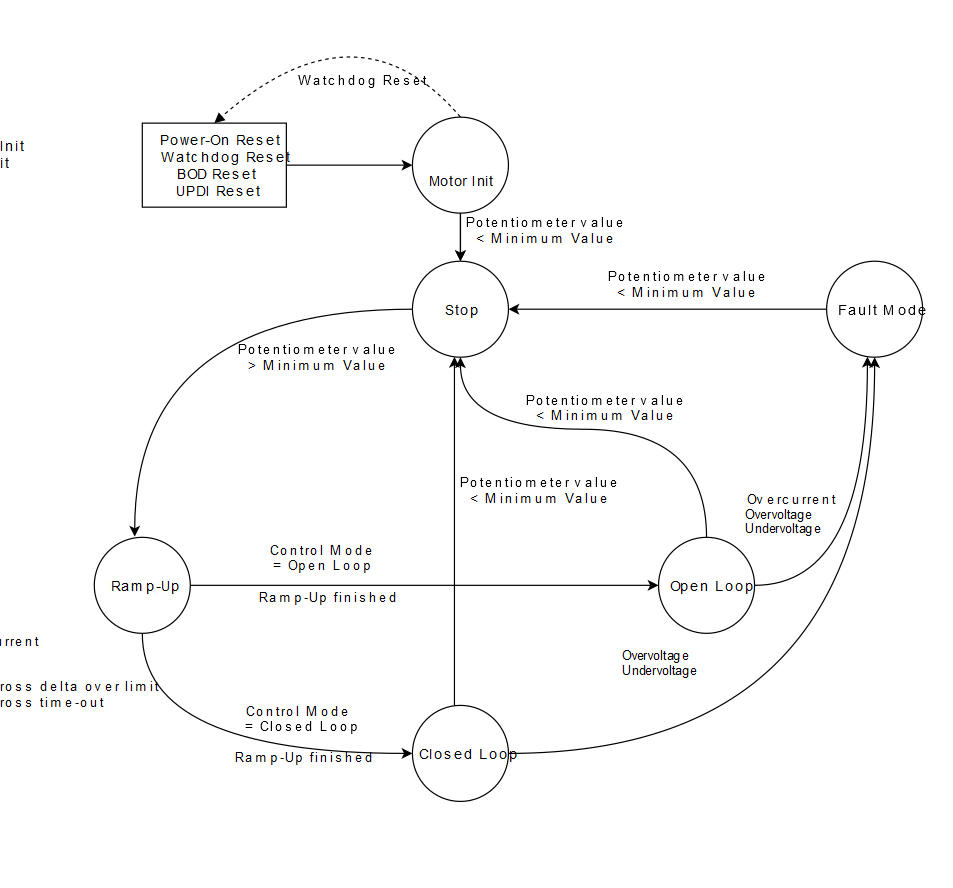
On system power-up, the System Control state is set to Driver Init, App Init state. This is the default state that the system has after any Reset. To identify the Reset cause, a message is printed to notify the user about the specific event. The potentiometer value is checked beforehand to make sure that the system does not start right up (for example, if the system had an external Reset while the motor was at full speed, it would not have started right up protecting the motor and power stage). If the condition is not met, the watchdog will trigger and reset the microcontroller.
After this, the motor enters the Stop state. If the potentiometer value increases above a set threshold, then the rotor will be aligned, and the system state will be set to Ramp-Up. Here, the motor is accelerated to the defined speed in software, without knowing the position of the rotor.
Upon finishing the ramp-up sequence, the system goes in the Defined Control state, which can be either Open Loop or Closed Loop.
When in Open Loop, the motor runs and the microcontroller does not have any information about its rotor position. The speed of the motor can be adjusted through the potentiometer. If its value is smaller than a set threshold, the motor stops and the system goes into the Stop state. If an overcurrent is detected, the system goes into the Error Handling state.
When in Closed Loop, the running of the motor is based on the feedback received by the microcontroller about the rotor position. The speed of the motor is constant and only the duty cycle can be adjusted through the potentiometer. If its value is smaller than a set threshold, the motor stops and the system goes into the Stop state.
Besides overcurrent, zero-cross delta over limit, zero-cross time-out, undervoltage and overvoltage cause the system to enter the Error Handling state.
If the system gets into Error state, then the only way to reset it is to get the potentiometer under a set threshold. Then the system gets back to the initial Stop state.
Overview of the Utilized Device Modules and Signals
Figure 2 depicts the relationship between the hardware, microcontroller and software modules. The term ‘control’ is used to signal any modifications on the peripheral’s registers.
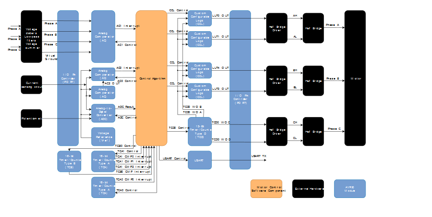
This implementation makes use of the bipolar switching presented above, and the zero-cross is detected by using an internal comparator.