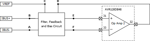
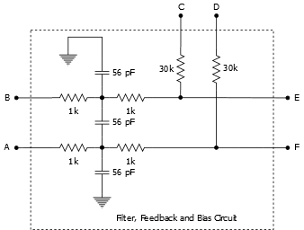
Analog Functionality

Table 1. Internal Op Amp Parameters
Op Amp # Analog Function Passive Components Design Equations
2 Low-pass filter R2, R3, R5, R6, C13, C14, C17

R2=R3=R5=R6=R

C13=C17=C

R1=R7

Commonmodef3dB12πRC

Differentialmodef3dB12π(2R)(C2+C14)

DifferentialamplifiergainR72R

Reference voltage bias R1, R7
Differential amplifier input R2, R3, R5, R6
Differential amplifier feedback R1
Figure 1. Internal Op Amp Configuration

Differentialamplifiergain=30kΩ2*1kΩ=15

Differentialmodef3dB12π(2*1kΩ)(56pF2+56pF)948KHz

Commonmodef3dB12π(1kΩ)(56pF)2.8MHz

Figure 2. Voltage Divider and Low-Pass Filter for Phase Back-EMF
Cutofffrequency3dB=12π(30k2k+300)10nF7321Hz
30degreephaseshiftfrequency=tan(30)2π(30k2k+300)10nF=4226Hz

Thus, the theoretical maximum speed of the motor will be:

4226Hz*60253560eRPM
MechanicalRPM=eRPM/Polepairs