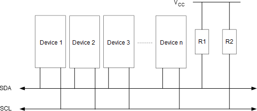
The Two-wire Serial Interface (TWI) is ideally suited for microcontroller applications. The TWI protocol allows the systems designer to interconnect up to 128 individually addressable devices using only two bi-directional bus lines; one for clock (SCL) and one for data (SDA). The only external hardware required to implement the bus is a single pull-up resistor for each of the TWI bus lines. All devices connected to the bus have individual addresses, and mechanisms for resolving bus contention are inherent in the TWI protocol.
The TWI bus is a multi-master bus where one or more devices are capable of taking control of the bus, can be connected. Only Master devices can drive both the SCL and SDA lines, while a Slave device is only allowed to issue data on the SDA line.
Data transfer is always initiated by a Bus Master device. A high to low transition on the SDA line, while SCL is high, is defined to be a START condition or a repeated start condition.

A START condition is always followed by the (unique) 7-bit slave address and then by a Data Direction bit. The Slave device addressed now acknowledges to the Master by holding SDA low for one clock cycle. If the Master does not receive any acknowledge the transfer is terminated. Depending on the Data Direction bit, the Master or Slave now transmits 8-bit of data on the SDA line. The receiving device then acknowledges the data. Multiple bytes can be transferred in one direction before a repeated START or STOP condition is issued by the Master. The transfer is terminated when the Master issues a STOP condition. A STOP condition is defined by a low to high transition on the SDA line while the SCL is high.
If a Slave device cannot handle incoming data until it has performed some other function, it can hold SCL low to force the Master into a wait-state.
All data packets transmitted on the TWI bus are 9 bits, consisting of one data byte and an acknowledge bit. During a data transfer, the master generates the clock and the START and STOP conditions, while the receiver is responsible for acknowledging the reception. An Acknowledge (ACK) is signaled by the receiver pulling the SDA line low during the ninth SCL cycle. If the receiver leaves the SDA line high, a NACK is signaled.