The Input Capture Register can capture the Timer/Counter value when a change of the logic level (an event) occurs on either the Input Capture pin (ICPn) or alternatively on the Analog Comparator output (ACO). To select the ICPn pin, the ACSR.ACIC should first be cleared to disable the Analog Comparator input capture function. Secondly, the users need to set the WGM[3:0] value for choosing the Timer/counter operation mode not using the ICRn register as Timer/counter TOP value. For more information about WGM[3:0] setting, see the table below.
| WGM[3:0] | Timer/Counter mode of operation | TOP |
|---|---|---|
| 0 | Normal | 0xFFFF |
| 1 | PWM,Phase Correct, 8 BIT | 0x0FFF |
| 2 | PWM, Phase Correct, 9 BIT | 0x01FF |
| 3 | PWM, Phase Correct, 10 BIT | 0x03FF |
| 4 | CTC | OCR4A |
| 5 | Fast PWM, 8 BIT | 0x00FF |
| 6 | Fast PWM, 9 BIT | 0x01FF |
| 7 | Fast PWM, 10 BIT | 0x03FF |
| 8 | PWM, Phase, and Frequency Correct | ICR1 |
| 9 | PWM, Phase, and Frequency Correct | OCR4A |
| 10 | PWM, Phase, and Frequency Correct | ICR1 |
| 11 | PWM, Phase, and Frequency Correct | OCR4A |
| 12 | CTC | ICR1 |
| 13 | Reserved | - |
| 14 | Fast PWM | ICR1 |
| 15 | Fast PWM | OCR4A |
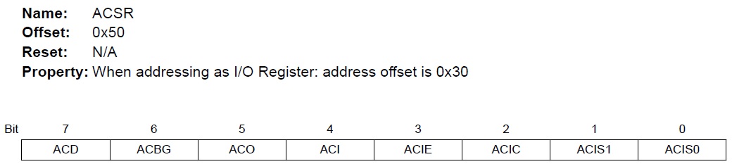
Bit 2 – ACIC: Analog Comparator Input Capture Enable
When written logic one, this bit enables the input capture function in Timer/Counter to be triggered by the Analog Comparator; When written logic zero, no connection between the Analog Comparator and the input capture function exists.