For TC0/1/3/4, the external clock source can be applied on the T0/1/3/4 pin by configuring the CS[2:0] bits of the TCCRnB register to "111" or "110".
Figure 1. Timer/Counter Control Register
B
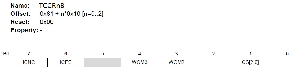
CS[2:0]—Clock selection bits description
| CS2 | CS1 | CS0 | Description |
|---|---|---|---|
| 0 | 0 | 0 | No clock source (Timer/Counter stopped) |
| 0 | 0 | 1 | clkI/O/1 (no prescaling) |
| 0 | 1 | 0 | clkI/O/8 (from prescaler) |
| 0 | 1 | 1 | clkI/O/64 (from prescaler) |
| 1 | 0 | 0 | clkI/O/256 (from prescaler) |
| 1 | 0 | 1 | clkI/O/1024 (from prescaler) |
| 1 | 1 | 0 | External clock source on T1 pin. Clock on falling edge. |
| 1 | 1 | 1 | External clock source on T1 pin. Clock on rising edge. |