On devices that use a Serial Peripheral Interface (SPI) for ISP, these lines are usually located on the same pins as a regular SPI, or on pins that can be used for other purposes. Refer to the device data sheet to determine the pins used for the ISP.
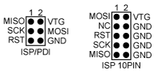
Two standard SPI connectors are provided by the ISP programmers; a 6-pin and a 10-pin connector. In addition to the data lines (MOSI and MISO) and the bus clock (SCK), the target voltage VTG, GND, and Reset (RST) are also provided through these connectors.
A few ISP programmers are powered by the target power supply. In this way they easily adapt to the correct voltage level of the target board. Other ISP programmers, such as STK600, can alternatively power the target board via the VTG line. In such a case, it is important that the power supply on the target is not switched on.