Most AVR microcontrollers operate over a wide voltage range and draw only a few mA of supply current. This may give the impression that the power supply is not critical but, as with any digital circuit, the supply current is an average value. The current is drawn in very short spikes on the clock edges. If I/O lines are switching, the spikes will be even higher. If all eight I/O lines of an I/O port change value simultaneously, the current pulses on the power supply lines can be several hundred mA. If the I/O lines are not loaded, the pulse may last for only a few nanoseconds.
Such a current spike cannot be delivered over long power supply lines; the main source should be the decoupling capacitor.
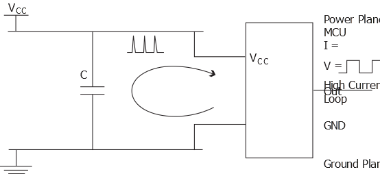
The figure above shows an example of insufficient decoupling. The capacitor is placed too far away from the microcontroller, creating a larger high-current loop. The power and ground planes are part of the high-current loop. As a result, noise is spread more easily to other devices on the board and radiated emission from the board is increased even further. The whole ground plane will act as an antenna for the noise, instead of only the high-current loop. This will be the case when the power and ground pins are connected directly to the planes (typical for hole-mounted components) and the decoupling capacitor is connected to the planes some distance away. This is sometimes observed in boards with surface-mount components where the integrated circuits are placed on one side of the board and the decoupling capacitors are placed on the other side.
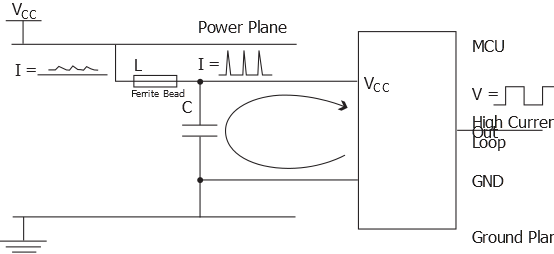
The figure below shows a better placement of the capacitor. The lines that are part of the high-current loop are not part of the power or ground planes. This is important, as the power and ground planes otherwise will spread a lot of noise. The figure also shows another method of improving decoupling; a series ferrite bead is inserted to reduce the switching noise on the power plane. The series impedance of the ferrite bead should be low enough to ensure that there is no significant drop in the DC voltage. The ferrite bead may not be necessary, especially if the power supply itself is sufficiently filtered.
Another decoupling alternative is to connect the device power and ground pins directly to the planes and connect the decoupling capacitor(s) to the planes as close as possible to the power and ground pins. For large packages, placing decoupling capacitors on the opposite side of the board may be the best way of getting them as close as possible to the power and ground pins. Also, in this approach, it is critical to minimize the loop area formed between the decoupling capacitor and device power and ground pin. The downside of this approach is that power plane noise can more easily be coupled to the device power supply - thus making sure that the power plane is properly filtered in general becomes more important.
In AVR devices, where power and ground pins are placed close together, there will be better decoupling than in devices with industry standard pinout. In industry standard pinout, the power and ground pins are placed in opposite corners of the DIP package. For devices with multiple pairs of power and ground pins, it is essential that there is a decoupling capacitor for every pair of pins.
The main power supply should also have a tantalum or ceramic capacitor to stabilize it.