The GPIO interface source is of type uint8, and contains the bit values of the enabled GPIO pins. A packet is transmitted every time a pin toggles. The sink sends values received back out to the GPIO pins. For further details on the physical part of the GPIO interface, see the user guide of the debugging tool to be used to sample the GPIO data.
The GPIO Configuration dialog is opened from the GPIO interface in the DGI Control Panel.

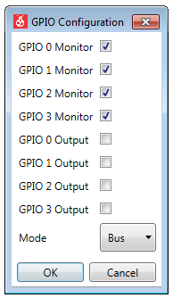
| Field Name | Values | Usage |
|---|---|---|
| GPIO 0 Monitor | ON, OFF | Monitor GPIO pin 0 |
| GPIO 1 Monitor | ON, OFF | Monitor GPIO pin 1 |
| GPIO 2 Monitor | ON, OFF | Monitor GPIO pin 2 |
| GPIO 3 Monitor | ON, OFF | Monitor GPIO pin 3 |
| GPIO 0 Output | ON, OFF | Enable GPIO pin 0 output |
| GPIO 1 Output | ON, OFF | Enable GPIO pin 1 output |
| GPIO 2 Output | ON, OFF | Enable GPIO pin 2 output |
| GPIO 3 Output | ON, OFF | Enable GPIO pin 3 output |
| Mode | Pin, Bus, Latched Bus | GPIO pins as separate pins, a 4-bit bus, or a 3-bit bus that is latched on rising edge of GPIO3 |
Important: When using any of the bus
modes (Bus or Latched Bus) all GPIOs are sampled but only those GPIOs that have
monitoring enabled will trigger a sample. For example, if GPIO 0 to GPIO2 all have GPIO
Monitor disabled but GPIO 3 has Monitor enabled, then GPIO values will only be sampled
when GPIO 3 changes but all four GPIO values will be read when GPIO 3 changes.