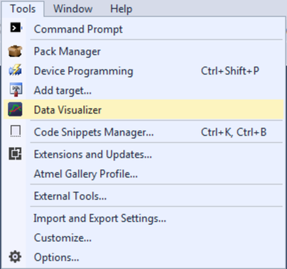
To demonstrate how to use the Oscilloscope module a light sensor target application will be used. The light sensor example is a rather generic data source where an Analog-to-Digital Converter is used to sample the sensor, and the example applies to a wide range of other data sources.
- Host computer with Atmel Studio 7 or later installed (Data Visualizer is included)
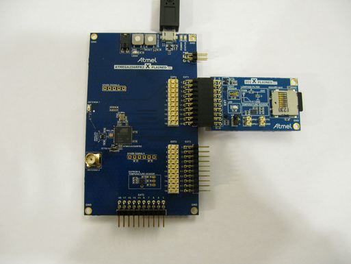
- ATmega256RFR2 Xplained Pro kit
- I/O1 Xplained Pro extension
- I/O1 Xplained Pro extension connected to ATmega256RFR2 Xplained Pro EXT1 connector
- USB cable connected from host computer to ATmega256RFR2 Xplained Pro
To be able to view the light sensor data in the Oscilloscope module, the ATmega256RFR2 target has to be programmed with code that samples the light sensor and sends the data to the Embedded Debugger (EDBG) on the ATmega256RFR2 Xplained Pro over a serial interface. The EDBG then uses the Data Gateway Interface (DGI) to send the data to the host computer.
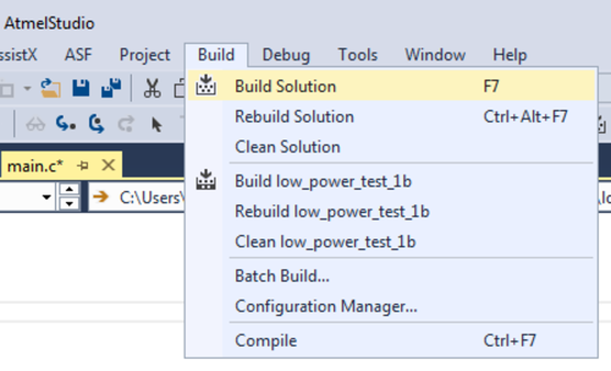
First, a new project for the target application code has to be set up in Atmel Studio.
- Make a new project in Atmel Studio (File → New → Project → GCC C Executable Project)
- Replace the content of the automatically generated main.c file with the code below
#include <avr/io.h>
#include <avr/interrupt.h>
uint16_t adc_value = 0;
volatile uint8_t send_data = 0;
void adc_init(void){
	// Internal 1.5V reference, ADC0 as single ended input
	ADMUX = (1 << REFS1);
	// Enable the ADC, auto triggered mode, interrupt on conversion finished
	ADCSRA |= (1<<ADEN) | (1<<ADATE) | (1<<ADIE);
	// Timer/Counter compare match A as trigger of ADC conversion
	ADCSRB |= (1<<ADTS1) | (1<<ADTS0);
	// Check that the reference is OK
	while (0x00 == (ADCSRB & (1 << REFOK)));
}
void spi_init(void){
	// Slave select (PB0), MOSI (PB2) and SCK (PB1) as output
	DDRB |= (1<<PINB0) | (1<<PINB2) | (1<<PINB1);
	//Slave select high (inactive)
	PORTB |= (1<<PINB0);
	// 2X mode, 4MHz SPI clock when CPU clock is 8MHz
	SPSR |= (1<<SPI2X);
	// Master mode, enable SPI module.
	// Clock polarity and phase is kept at default (Sample on rising edge)
	SPCR = (1<<SPE) | (1<<MSTR);
}
void spi_send(uint8_t data){
	// Slave select low
	PORTB &= ~(1<<PINB0);
	// Write data to shift register
	SPDR = data;
	// Wait for the transmission to complete
	while (0x00 == (SPSR & (1<<SPIF)));
	// Slave select high
	PORTB |= (1<<PINB0);
}
void timer_init(){
	// Set TOP value for timer (output compare A value)
	OCR0A = 80;
	// Clear timer on compare match mode
	TCCR0A = (1<<WGM01);
	// Timer clocked by CPU clock, no prescaler
	TCCR0B = (1<<CS00);
}
ISR (ADC_vect){
	// Store the light sensor sample
	adc_value = (ADC);
	// Clear timer interrupt flag to enable the next sample
	TIFR0 |= (1<<OCF0A);
	// Flag sending of data to host
	send_data = 1;
}
int main(void){
	timer_init();
	adc_init();
	spi_init();
	// Interrupts on
	sei();
	while (1){
		if (1 == send_data){
			send_data = 0;
			// Send the ADC value over SPI to the host
			// Only the 8 lower bits contain useful data
			spi_send(adc_value & 0xFF);
		}
	}
}
The code configures the ADC to take a new sample every 10th μs giving a sample rate of 100 kHz. This is achieved by using a timer that counts up to 80 before resetting. The code is based on the target CPU running on the internal 16 MHz clock with a clock prescaler of 2 (default) and the CKDIV8 fuse not set. The data samples are sent to the EDBG over the DGI SPI interface. The SPI interface is running at 4 MHz. The ATmega256RFR2 ADC is 10-bit but only the lower 8 bits contain useful data in this example.
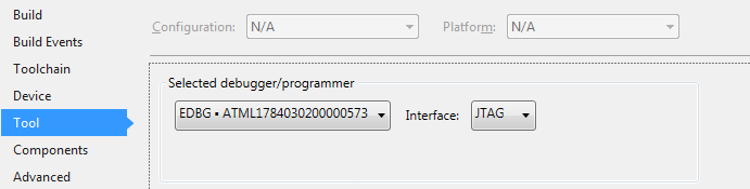
- Open the project properties (right click the project in the Solution Explorer and select Properties)
- On the Tool tab, select the appropriate tool and interface