The ACT increases the accuracy of the HFINTOSC by continuously updating the OSCTUNE register. To compare the accuracy of the instruction clock, data was collected across temperature (-40°C to 125°C) and voltage (2.3V to 5.5V). The first test case demonstrated the instruction clock accuracy without ACT enabled, followed by the second test case to show the clock accuracy with ACT enabled. The preliminary data was collected from several PIC16F19186 devices with HFINTOSC set for 8 MHz operations and the clock divider set to 4 for a system clock of 2 MHz.
The SOSC oscillator used was an NDK NX2012SA-32.768K-STD-MUB-1 crystal with two Panasonic ECJ-1VC1H090D 9pF, 50V, NP0, 0603 sized ceramic capacitors. User results will be different with other crystal, capacitors, or if there is a load resistor (Rs) in series with the crystal. The variation of the crystal frequency over voltage and temperature will also affect the accuracy.
Figure 1 shows the percentage of deviation in frequency over temperature at different voltages, ranging from 2.3V to 5.5V, centered at 25°C with ACT disabled. Figure 2 shows the same information with ACT enabled. Notice the percentage of deviation is ±0.07% with ACT enabled. This is significantly less than the nominal value stated in the datasheets for PIC16(L)F191XX devices. These results were obtained with the specific crystal, capacitors, and PCB used in the data collection and user results will vary.


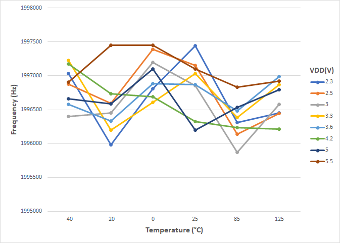
Figure 3 shows the change in frequency over temperature at common systems voltages ranging from 2.3V to 5.5V, with ACT disabled. In Figure 4 the same information was collected with ACT enabled. Here it is shown that with ACT enabled the deviation in frequency across temperature and voltage is less than with ACT disabled.