4 Implementation
The example implementation for the ATtiny416 is written in C. The two key modules used are the Real-Time Counter (RTC) and the 16-bit Timer/Counter Type B (TCB). The Event System (EVSYS) is also used to connect the output of the RTC to the input of the TCB. With proper configuration of the RTC, EVSYS, and TCB, the TCB can be used to count the number of 32.768 kHz external crystal oscillator cycles between consecutive overflow events from the RTC.
The clock of the RTC is configured to be the OSCULP32 divided by 32, for a nominal clock frequency of 1024 Hz. The RTC prescaler is configured with one, and the RTC.PER (period) register is configured with (3*1024)-1 = 3071, so the RTC will generate an overflow interrupt/event approximately every three seconds. The RTC RUNSTDBY bit is configured to one so that the RTC will continue running while the device is in sleep mode.
The EVSYS is configured with the RTC overflow event connected to the TCB input.
The TCB is configured with its clock source as the main clock of the device with no prescaling. When a measurement is in progress, the main clock of the device is the 32.768 kHz external crystal oscillator. The TCB count mode (CNTMODE) is configured as input capture frequency measurement, and the capture event input (CAPTEI) is enabled. With this configuration, the TCB will capture and store its count value at each RTC overflow event, then reset its counter. This allows the TCB to effectively count the number of 32.768 kHz clock cycles between consecutive input events. Because the TCB counter is only 16 bits wide (maximum count of 65535) and there will be roughly 3s*32768 Hz = 98304 clock cycles between ticks, the TCB counter will have overflowed once during the measurement. Thus, 65536 must be added to the value read from the TCB capture register to obtain the true number of counts between consecutive events.

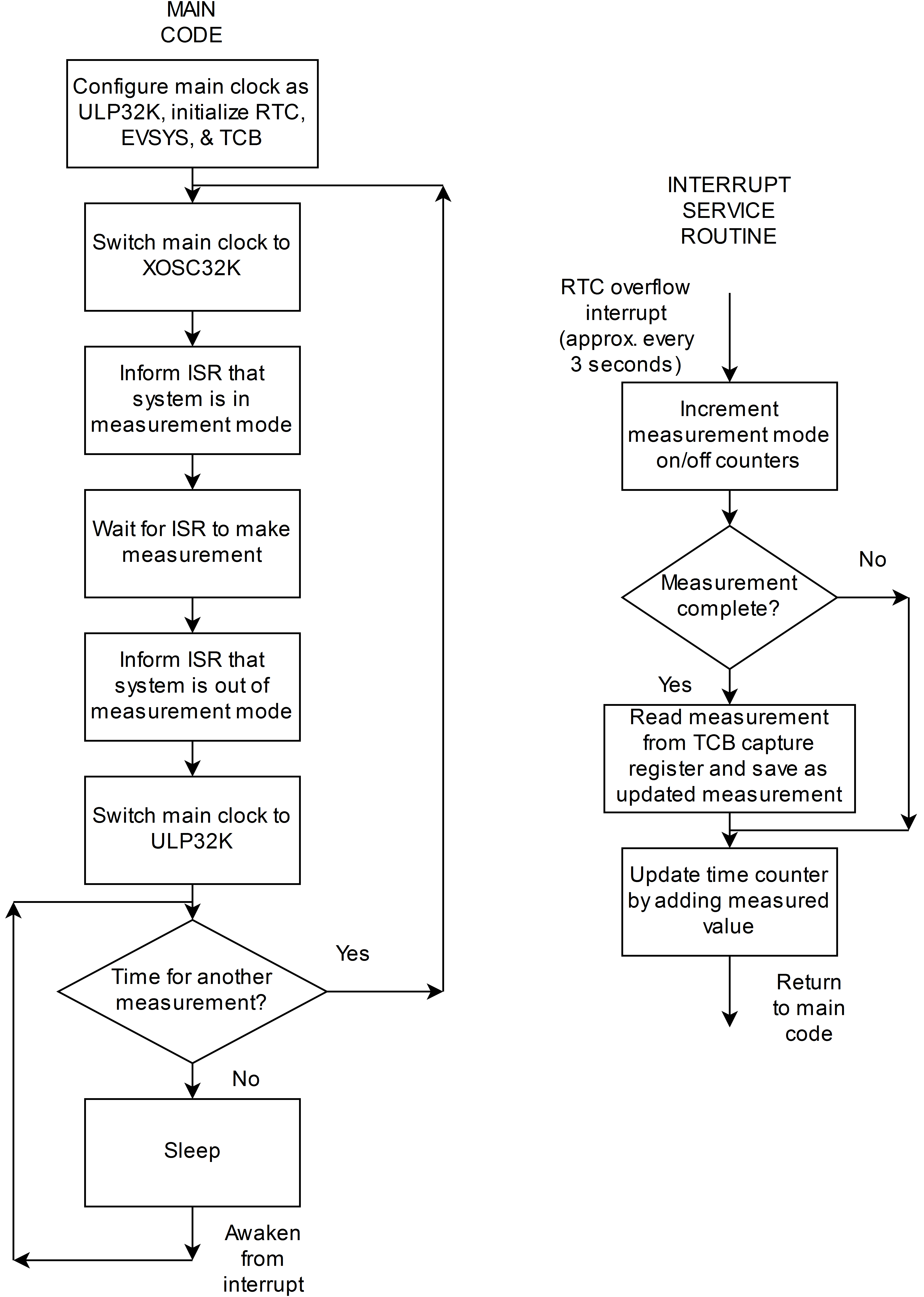
- The main clock of the device is switched to the internal 32.768 kHz ULP oscillator (OSCULP32K). By default, the device starts up with a different main clock, so the main clock must be explicitly changed. The main clock provides the clock to the CPU, RAM, NVM, and many peripherals. The RTC, EVSYS, and TCB are configured as described earlier so that the TCB can measure the interval between successive RTC overflow interrupts/events.
- The main clock of the device is switched to the external 32.768 kHz crystal oscillator (XOSC32K). The crystal oscillator is allowed a two-second start-up time to become stable, so there will be about two seconds before the main clock is actually switched.
- The value of a variable is changed to indicate to the RTC ISR that the system is now in Measurement mode.
- The main code waits for the interrupt service routine to read the captured value (measurement) from the TCB.
- After the main code detects that the measurement is complete, it changes the value of a variable to indicate that system is not in Measurement mode.
- The main clock of the device is switched back to OSCULP32K. Since nothing is using the crystal oscillator (XOSC32K), it will be disabled automatically by hardware in the device to save power.
- The RTC ISR counts the number of RTC ticks that have occurred while the system is not in Measurement mode. The CPU remains in sleep mode until the number of RTC ticks reaches 300 (approximately 900 seconds or 15 minutes). When it is time for another measurement, the CPU goes back to step two.
- Counters are incremented to keep track of how many RTC interrupts have occurred while not in Measurement mode and while in Measurement mode.
- If two ticks have occurred while in Measurement mode, a new measurement is complete, so the captured count is read from the TCB and saved in a variable. Because the TCB is only 16 bits wide (maximum count of 65535) and there will be approximately 3s*32768 Hz = 98304 clock cycles between ticks, the TCB will have overflowed once during the measurement. Thus, 65536 must be added to the measurement to account for this. Once this has been done, the measurement represents the precise number of 32.768 kHz crystal oscillator cycles in each RTC tick.
- The measurement is added to a counter that keeps track of time in terms of (1/32768)s = 30.518 μs units.
One important consideration in this example is the choice of duration between consecutive ticks of the RTC. Since a 32768 Hz clock is being used to measure the duration, using a one-second RTC tick would have led to only (1/32768) or 31 ppm resolution in measuring the tick duration. This could have led to errors on the order of several seconds per day. A three-second RTC tick was therefore chosen in order to improve the measurement resolution to (1/(3*32768)) or 10 ppm. However, this also meant that the 16-bit TCB counter would overflow once while making a measurement, so 65536 must always be added to the TCB result to get the true measurement value.
Depending on the detailed requirements of the application, it is possible that the 16-bit Timer/Counter Type A (TCA) could be used to count RTC events or ticks instead of using an RTC ISR for this purpose. This could provide additional power savings since the device would remain in sleep mode for longer periods of time. The TCA could be programmed, for example, to generate an interrupt every 20 RTC ticks, which is one minute.
