1 MPLAB® Harmony Smart Energy PRIME Stack
The Smart Energy PRIME Stack is the Microchip implementation of the PRIME standard (PRIME = PoweRline Intelligent Metering Evolution). It is a Smart Metering solution which provides communication capabilities using PLC (PowerLine Communication). In case of PRIME v1.4, it also provides access to RF medium.
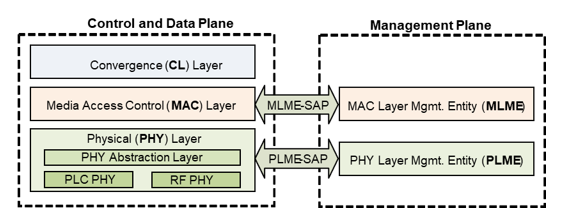
The following image shows the complete PRIME protocol stack:

PRIME in a Nutshell
PRIME is a OFDM-based power line communication system for the provision of all kinds of Smart Grid services over electricity distribution networks. It includes PHY and MAC layers according to IEEE conventions, plus a Convergence layer. There are two versions: PRIME v1.3.6 and PRIME v1.4. PRIME v1.4 offers advanced functionalities, including secondary radio frequency (RF) medium. The RF physical layer is based on SUN (Smart Utility Network) FSK, as specified in IEEE 802.15.4-2015.
- A PHY layer capable of achieving rates of uncoded 1Mbps on the PLC medium.
- A PHY layer capable of achieving SUN FSK Operating Mode 2 data rates on the RF medium.
- A MAC layer for the power line and RF environments.
- A Convergence layer (CL) for adapting several specific services.
- A Management Plane for operations and control.
The PHY layer transmits and receives MPDUs between Neighbor Nodes using PLC or RF depending on the capability of devices and characteristics of the medium. The PHY layer in PLC is based on OFDM (Orthogonal Frequency Division Multiplexing) and Differential Phase Shift Keying (BPSK, DQPSK and D8PSK) as carrier modulation. To address averse power line channel properties, robustness mechanism convolutional encoding (optional), scrambling and interleaving are used. PRIME v1.4 also introduces repetition coding as additional robustness mechanism.
The MAC layer provides core MAC functionalities of system access, bandwidth allocation, connection establishment/maintenance (unicast, multicast and broadcast connections) and topology resolution. To provide reliable connections, Selective Repeat ARQ is used between the two connection end points. PRIME specifies a security profile for encryption of MAC layer packets. Encryption is based on AES-CCM with 128bit keys and key derivation mechanism recommended by NIST.
The CL classifies traffic associating it with its proper MAC connection; this layer performs the mapping of any kind of traffic to be properly included in MPDUs. It may also include header compression functions. This is included in the CPCS (Common Part Convergence Sublayer). To accommodate different kinds of traffic into MPDUs, PRIME specifies several SSCSs (Service Specific Convergence Sublayer).
The Management Plane specifies interfaces for local and remote management of nodes and for firmware upgrade.
A PRIME subnetwork can be logically seen as a tree structure with two types of Nodes: the Base Node and Service Nodes.
- Base Node: It is at the root of the tree structure and it acts as a master node that provides all subnetwork elements with connectivity. It manages the subnetwork resources and connections. There is only one Base Node in a subnetwork.
- Service Node: They are either leaves or branch points of the tree structure. They are initially in a disconnected functional state and follow the registration process to become part of the subnetwork. Service Nodes have two functions in the subnetwork: keeping connectivity to the subnetwork for their application layers, and switching other Service Nodes’ data to propagate connectivity.
PRIME Implementation in Harmony
The mechanisms and functionalities of the PRIME specification are the basis for the entire Harmony Smart Energy PRIME Stack implementation in Harmony. Therefore, it is highly recommended to use it as a reference. Basic concepts that are introduced by the PRIME specification are assumed to be known within this document.
The PRIME Stack general architecture follows the suggested separation of the network stack into logical layers, as described in the PRIME specification. Besides the core stack containing the protocol implementation, the PRIME general architecture contains additional layers implementing services (for example, serial interfaces), drivers (for example, the PLC PHY) and a user application example.
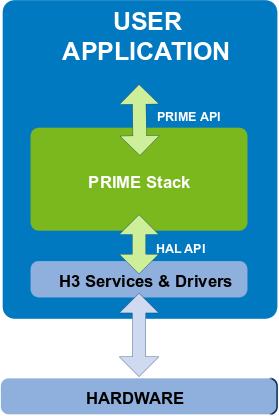
The general architecture of a user application including the PRIME Stack is shown in the next figure.

The PRIME Stack comprises the PRIME Library and the PRIME PAL. The PRIME Library contains the MAC layer, the Convergence Layer and the Management Plane as described in the PRIME specification. In a Base Node, it also includes a proprietary Base Management module to handle the interface between the Base Node and the DCU user application and enhance it with additional functionalities. Physical layers are also part of the Harmony 3 ecosystem, but are considered besides PRIME Stack, not part of it.
It is important to note that the only entry point to the PRIME Stack from the user application is through the PRIME API, which contains the interfaces defined in the PRIME specification as well as stack control functions. The PRIME Stack accesses the services and drivers in the Harmony 3 ecosystem with the HAL API.
The following figures show the architecture of the PRIME Stack.
The PRIME Library in a Base Node is provided a single library file integrated in the user application.
The PRIME Stack in a Service Node has been implemented with separated software modules as a way to optimize hardware resources and provide flexibility and versatility to the final user system. Following this concept, the user application and the PRIME Library have separated binary images. Additionally, there is a third binary image in the PLC PHY Driver corresponding to the PL360 firmware.
- The PRIME Stack is highlighted in red.
- The PLC PHY Driver is highlighted in yellow.
- The RF PHY Driver is highlighted in green.
- The Firmware Upgrade Service in highlighted in blue.
Double clicking on the PRIME Stack block, the PRIME Stack View is opened, and there, the different implementation modules are presented:
-
The PRIME Stack block highlighted in red corresponds to the PRIME Library described before.
-
The PAL block highlighted in green is a module in charge of adapting the MAC layer to the Drivers below. This provides an abstraction from the MAC layers to the Physical layers, so by changing the PAL contents different PHYs (transceivers) can be used.
-
The PRIME Auxiliary Services are highlighted in blue, they provide the following:
Figure 1-7. PRIME Services View - SE Random. Abstracts the generation of random numbers, so the PRIME Stack has a single API to generate random values, whathever the below implementation.
- SE CRC. Same as Random, provides an abstraction API for CRC calculation.
- SE Security. Same as Random, abstracts a unique API from the security implementation below.
- SE Queue. Implements a queing mechanism used by the PRIME Stack that can be shared with other modules.
- SE Log Report: PRIME Stack code uses a tracing mechanism that outputs logging messages to a Console. This Service implements the connection to the Console, or turns functions into empty code in case tracing is not enabled.
- PRIME Storage: Same as Random, abstracts a unique API to store non-volatile information.
- User PIBs: Implements the handling of a parameter interface base defined by the user.
- Reset Handler: Implements an interaface to trigger system resets and to store reset causes.
- Time Management: Implements an interface to the System Time module.
- Firmware Upgrade: Implements the handling of firmware upgrade and the version swap of Service Nodes. This Service can be found in the main window of the MCC Project Graph due to its mandatory connection to the Memory Driver.
