
6.1 MCC Configuration for Diagnostics Module
Device Support
The following ATtiny 161x/321x-series devices are supported for Diagnostics Module generation in the MCC Melody v4.6.0.
| Series | Device Support |
| ATtiny 161x-series | ATtiny 1616, ATtiny 1617 |
| ATtiny 321x-series | ATtiny 3216, ATtiny 3217 |
Diagnostics Module
Touch solutions require a high level of reliability for best performance and satisfying user experience. The Acquisition module and other post processing modules such as keys, and frequency hop auto-tune provide all that is required for a great touch interface. However, there are times when a physical fault on the PCB results in the malfunction of the touch device. The level of malfunction can be very serious, as it may trigger an unwanted touch or not detect a normal touch. To reduce errors in such a scenario, the Diagnostics module was developed. The application can include Diagnostics to detect faults that occur at pin level.
The Diagnostics components are present in the Diagnostics module. This module, when included with the application project files and used appropriately, checks for pin faults and presents the result in a relevant format. Analysis of pin faults is performed only on pins which are used for touch sensing. Pins which are not used for the touch application are not checked under this analysis. It is up to the application to use these results and take appropriate actions.
This module is used to detect faults in the device port pins used for touch sensing. Examples of such faults are as follows:
- Pin short toVCC
- Pin short to Vss
- Pin short to otherpin
- Pin not connected to touch sensorelectrode
The Diagnostics module reports faults, such as short to VCC,VSS, between Pins Short, and sensor connection test failure and the faulty channels and pins.
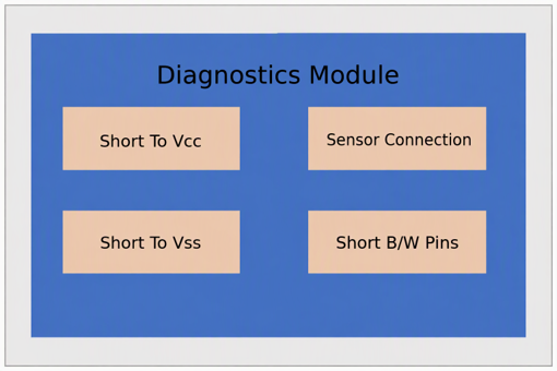
MCC Configuration for Diagnostics Module generation
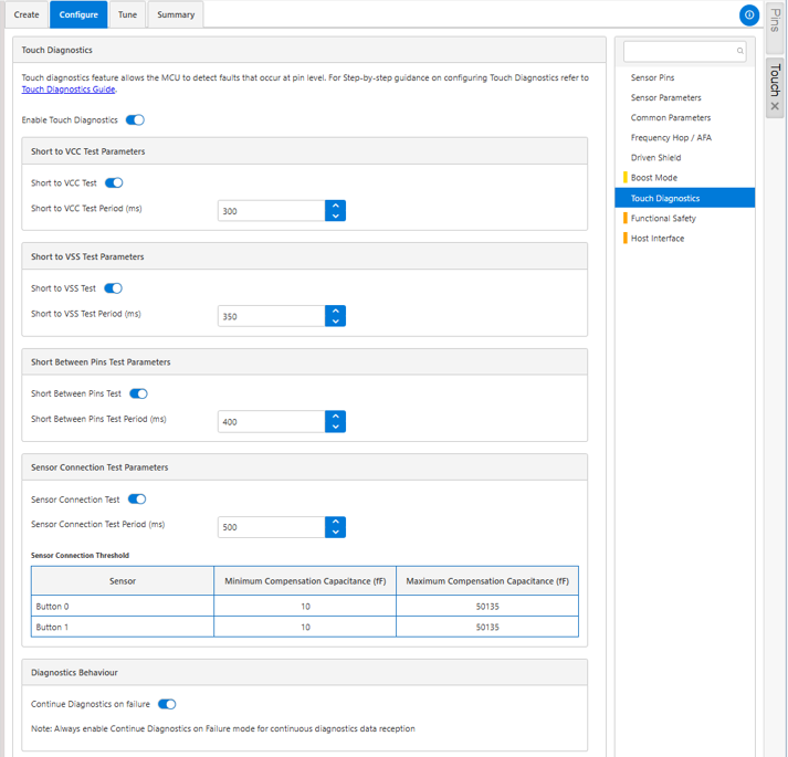
Enable Touch Diagnostics
Enable Touch Diagnostics option shall be toggled to expand the four diagnostics tests – Short to Vcc test, Short to Vss test, Short between pins test and Sensor connection test. As shown in the figure below, each diagnostics test has respective Enabler option. Enabling the required test will expand to configure the test period in milliseconds(ms) and additional parameters such as Sensor connection threshold (Minimum compensation capacitance and Maximum compensation Capacitance) in the case of Sensor connection Test. In addition to the diagnostics tests, Continue Diagnostics on failure provides the option to receive the diagnostics data post fault detection if enabled.
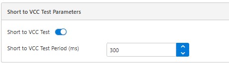
Short to Vcc Test
Short to Vcc Test enabler should be toggled to test periodically whether there is any Vcc short occurred to the touch pins. The test period could be provided in the number input box.
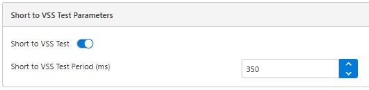
Short to Vss Test
Short to Vss Test enabler should be toggled to test periodically whether there is any Vss short occurred to the touch pins. The test period could be provided in the number input box.
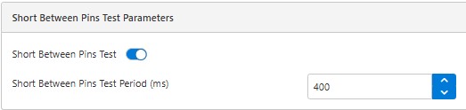
Short between pins Test
Short between pins Test enabler should be toggled to test periodically whether there is a short between touch pins. The test period could be provided in the number input box.
Sensor Connection Test
Sensor connection test enabler should be toggled to test periodically whether there is a disconnection in the touch pins connected to the MCU. This test compares the at present calibrated compensation capacitance (CC) value against the limits that was defined for a valid channel. The time for periodically performing this test is provided in the number input box.
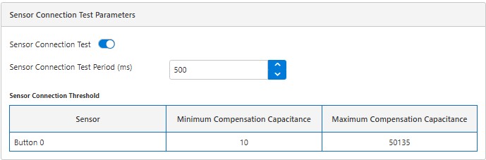
Configuring Min. and Max. Compensation Capacitance Threshold for Sensor ConnectionTest
Identify the compensation capacitance (CC) of each sensor after calibration with the sensor board connected. Then the minimum and maximum CC value for the sensor shall be 30% below and 30% above that noted value. Any deviation beyond 30% can be considered an error.
For example, if the compensation capacitance value after calibration is 10 pF, then the min and max value threshold may be configured as 7 pF as a lower limit and 13 pF as an upper limit. Note that this is just an example recommendation, there could be a possibility that 30% might not be enough, it could be on the higher side or the lower side, based on product testing.
Application Consideration
Sensor Connection Test
Faults such as shorts to VCC, VSS, or other pins can push the CC value beyond the defined limits. Therefore, if the sensor connection test runs before the specific fault test, the fault may be reported as sensor connection test error.
For example, assume that a pin is short to VCC; this error can lead to sensor connection failure. This error can be detected if the short to VCC test is performed. If the sensor connection test is performed before the short to VCC, then sensor connection error may occur. In an application, the Diagnostics test may run at various time intervals and if an error is introduced at run time, there is a possibility that the error is reported as sensor connection error.
Compensation Capacitance Threshold for Sensor Connection Test
Calculating the compensation capacitance value when a sensor is touched will give different values compared to when it is not touched. Similarly, the compensation capacitance value may change due to temperature and other environmental factors. Since the sensor connection test may be called while touching the sensor electrode or at different temperature levels, the user should consider tolerances while configuring min. and max. values, otherwise the sensor connection test may report false errors.
The application may also not run the sensor connection test when the sensor is touched if the change in CC values is very high in terms of percentage.
Note:
- In Diagnostics, the set number of acquisition should not be zero. At least one acquisition set needs to be present for touch functionality.
- For a self-cap driven shield enabled sensor, the sensor electrode may result in only a small change in the compensation capacitance when the sensor is disconnected. Therefore, the sensor connection test will be performed with the shield disabled, and the Min and Max compensation capacitance thresholds must be calculated with the driven shield disabled.
- Incase of driven shield, if a Y line channel is faulty, the pins on the X field of the node parameter would also be reported as faulty.
- A short between X lines after the series resistance could be identified by converting the mutual cap X lines to self cap Y lines. The application must create a new self-cap set with these converted Y lines and the Sensor connection test on these Y lines will identify the fault.
- While the system is in auto-scan, by default DIAG test will be done only during the drift wakeup, because the timer is configured for drift period. Users can configure the drift period as DIAG test period or use another timer for Diagnostics periodic wakeup to conduct the Diagnostics test as per the configured periodic intervals.
- Touch pins shorted to Vcc, Vss or between pins after the series resistance may not be identified by the respective tests. These faults will be identified by Sensor connection test as the sensor connection error.