4.1 Hardware Identification System
All extension boards come with an identification CryptoAuthentication™ chip (ATSHA204A) to uniquely identify the boards that are connected to the microcontroller evaluation kit. This chip contains information that identifies the extension with its name, and some extra data. When an extension kit is connected to an microcontroller evaluation kit, the information is read and sent to Atmel Studio/MPLAB X. The following table shows the data fields stored in the chip ID with example content.
| Data Field | Data Type | Example Content |
|---|---|---|
| Manufacturer | ASCII string | Microchip’\0’ |
| Product name | ASCII string | Segment Curiosity Nano Adapter’\0’ |
| Product revision | ASCII string | 01’\0’ |
| Product serial number | ASCII string | 3338011800000001’\0’ |
| Minimum voltage [mV] | uint16_t | 3300 |
| Maximum voltage [mV] | uint16_t | 5000 |
| Maximum current [mA] | uint16_t | 45 |
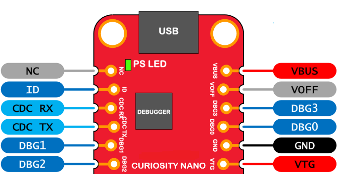
The twelve edge connections closest to the USB connector on Curiosity Nano kits have a standardized pinout. The program/debug pins have different functions depending on the target programming interface, as shown in Table 4-1 and Table 4-2.
| Debugger Signal | ICSP™ Target | Description |
|---|---|---|
| ID | - | ID line for extensions. |
| CDC TX | UART RX | USB CDC TX line. |
| CDC RX | UART TX | USB CDC RX line. |
| DBG0 | ICSPDAT | Debug data line. |
| DBG1 | ICSPCLK | Debug clock line/DGI GPIO. |
| DBG2 | GPIO0 | DGI GPIO. |
| DBG3 | MCLR | Reset line. |
| NC | - | No connect. |
| VBUS | - | VBUS voltage for external use. |
| VOFF | - | Voltage Off input. |
| VTG | - | Target voltage. |
| GND | - | Common ground. |

