
2 Power Supply
Power Supply, Power Measurement.
The MTCH9010 Evaluation Kit’s power supply features:
Tip: Select between 3.3V or 5.0V by changing position of the jumper on header J201. |  |

There are two main power domains available on the MTCH9010 Evaluation Kit.
| Power Domain | Vnom [V] | Vmin - Vmax [V] | Imax [mA] |
|---|---|---|---|
| VCC_P5V0 | 5.0 | 4.4-5.5 | 500 |
| VCC_P3V3 | 3.30 | 3.23–3.37 | 150 |
Info: VCC_P3V3 is connected to VCC_BRIDGE via a reverse blocking power switch and is subject to the same limitations.
Current Limiting Switch
A MIC2008 current limiting switch with an adjustable slew rate is mounted on the board to mange power start-up and prevent large inrush currents. The switch has been configured with the following limits using external components on the board:
- Slew rate: 2 V/ms
- Current limit: 500 mA
Info: MIC2008 current limit range: 0.2–2.0A.
The current limit and slew rate are set using external components on the board:- Slew rate: C205
- Current limit: R205
Power Sources
The MTCH9010 Evaluation Kit supports multiple power sources, select the desired power source by moving the provided jumper cap on the 1x3-100mil header J201 to the desired source as indicated on the silkscreen:
- USB-C® Power: The board can be powered directly from the USB-C connector. Power passes through the slow-start and current-limiting circuit, and the supply voltage depends on the USB input, which is typically 5.0V.
- 3.3V Regulator MCP1754/3.3V: The MCP1754 provides a stable 3.3V output to the board. It features robust input capabilities, protecting the board from short circuits and transient voltage events.
Tip: The characteristics of VCC_SYSTEM depend on the power source to which it is connected, either VCC_P5V0 or VCC_P3V3.
Edge Connector
System power is available for user peripherals via the 1x7-100 mil header (J100). This header can also be used to power the board externally or provide power to connected devices.
Important: When powering the board externally through header J100, the user must remove the jumper cap on header J201 to prevent potential damage to the board.
DANGER: There is no polarity protection on header J100. Ensure correct polarity when connecting power to avoid potential damage to the board.
2.1 MTCH9010 Power Measurement
The power consumption of the MTCH9010 can be measured using header J101. To do so, remove the jumper cap and connect your measuring instrument, as seen below. The evaluation kit is designed to ensure that the current through header J101 reflects only the actual current consumption of the MTCH9010. | 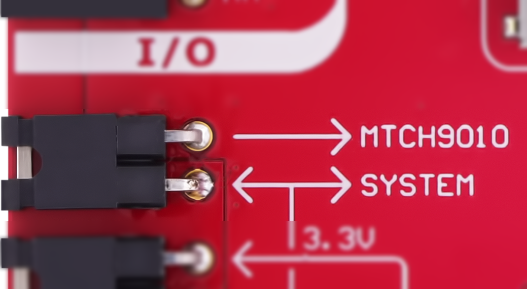 |

Tip: See the MTCH9010 data sheet for detailed electrical characteristics.
DANGER: Ensure the board is powered off when removing the jumper from header J101. Removing the jumper while the board is powered may cause the MTCH9010 to be powered through its input pins, potentially damaging the device.