
9.1 Timing Specifications
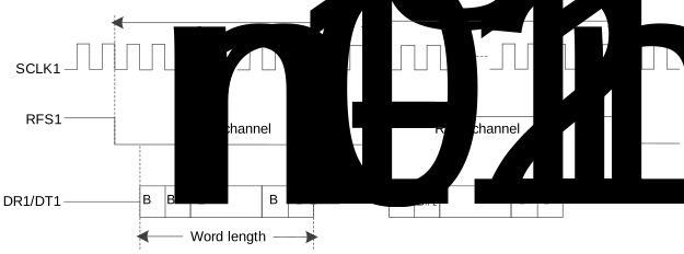
The following figures illustrate the timing diagram of the IS2083BM/BM83 in I2S and PCM modes.
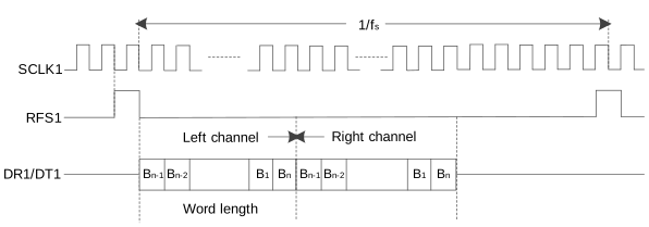
The following figure illustrates the timing diagram of the audio interface.
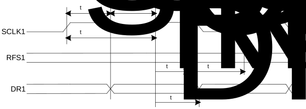
The following table provides the timing specifications of the audio interface.
| Parameter | Symbol | Min. | Typ. | Max. | Unit |
|---|---|---|---|---|---|
| SCLK1 duty ratio | dSCLK | — | 50 | — | % |
| SCLK1 cycle time | tSCLKCY | 50 | — | — | ns |
| SCLK1 pulse width high | tSCLKCH | 20 | — | — | ns |
| SCLK1 pulse width low | tSCLKCL | 20 | — | — | ns |
| RFS1 setup time to SCLK1 rising edge | tRFSSU | 10 | — | — | ns |
| RFS1 hold time from SCLK1 rising edge | tRFSH | 10 | — | — | ns |
| DR1 hold time from SCLK1 rising edge | tDH | 10 | — | — | ns |
- Test Conditions: Client mode, fs = 48 kHz, 24-bit data and SCLK1 period = 256 fs