3.7 EVSYS - Event System
3.7.1 Introduction
The Event System (EVSYS) enables direct peripheral-to-peripheral signaling. It allows a change in one peripheral (the event generator) to trigger actions in other peripherals (the event users) through event channels, without using the CPU. It is designed to provide a short and predictable response time between peripherals, allowing for autonomous peripheral control and interaction, and for synchronized timing of actions in several peripheral modules. Thus, it is a powerful tool for reducing the complexity, size, and execution time of the software.
There are no API for the Event System, rather some use cases are provided as configuration examples.
Features:
- System for Direct Peripheral-to-Peripheral Signaling
- Peripherals Can Directly Produce, Use, and React to Peripheral Events
- Short and Predictable Response Time
- Up to 10 Parallel Event Channels Available
- Each Channel is Driven by One Event Generator and Can Have Multiple Event Users
- Events Can be Sent and/or Received by Most Peripherals and by Software
- The Event System Works in Active, Idle, and Standby Sleep Modes
3.7.2 Supported Device Families
| AVR® Dx | AVR® Ex | ATtiny | ATmega |
3.7.3 Required Header Files
#include "mcc_generated_files/evsys/evsys.h"3.7.4 How to Use the AVR Event System
The links below provide examples for the different use cases for the Event System, which in all cases involve other peripherals. A more efficient refactoring is achieved in the Event System versions of these use use cases (shown in BOLD):
- RTC Use Case 1: 100 ms LED blink every 1s
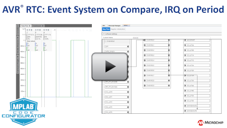
- RTC Use Case 2: Event System Pulse on Compare, Interrupt on 1s Period Using the Event System a pulse is generated on a RTC compare match of 200 ms.
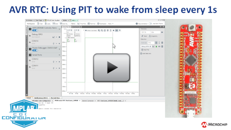
- RTC Use Case 3: Using RTC's PIT to Wake from Sleep The Periodic Interrupt Timer (PIT) function of the RTC to wake up the CPU. Every second a PIT interrupt wakes the AVR from Power Down mode, then in the PIT callback a LED is toggled, before we put the CPU to sleep again.
- RTC Use Case 3.5: Using the RTC's PIT with the Event System Refactoring the application, demonstrating how the Periodic Interrupt Timer works with the Event System. The same functionality, of a LED toggling every second is kept, without any code running.
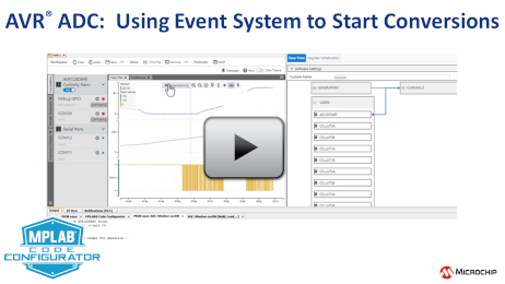
- ADC Use Case 3: Windowed ADC, on RTC overflow An ADC conversion is started in a Real-Time Counter (RTC) overflow callback. The ADC is configured in Window mode, only taking samples when < 1v or > 2.5v.
- ADC Use Case 3.5: Event Triggered ADC Conversions Refactoring the above use case to use the Event System (EVSYS) to trigger ADC conversions. Since the EVSYS makes direct hardware connections between the peripherals, the RTC callback (and its registration) can be removed.
- Recommended starting point: UART Driver, Timer/Counter A PLIB Driver and the Data Streamer Library.
- Videos also included for: RTC PLIB Driver, ADC PLIB Driver, AVR Event System.


