In this video and hands-on training: After demonstrating
MPLAB X's new active kit detection, the kit schematic is located and a new standalone
project for the ATmega324PB is created in MPLAB X. The datasheet is used to understand
how to set PC7 as OUTPUT, LOW. Then debugging is used to verify functionality.
Overview and objectives
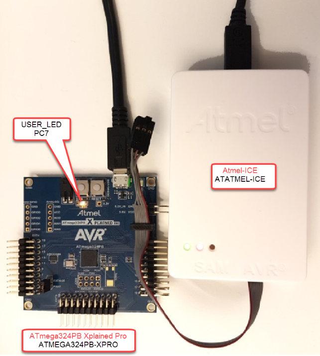
We will build a basic program for the ATmega324PB AVR MCU from scratch. The
objective is to turn on the kit's USER_LED, as shown in the following image, then to
toggle this LED every second.
For existing AVR users used to working in Atmel Studio
7, some of the similarities and differences with MPLAB X are
emphasized.
For existing PIC MCU users of MPLAB X, an overview of
AVR bare-metal programming references is given (listed below). For each of
these references, an attempt is made to show how each one is used in the
typical process of writing AVR code.
When the ATmega324PB Xplained
Prokit is plugged into MPLAB X, a welcome page for the kit
opens, with key links to find related technical information.
New Project Wizard
The new project wizard can be opened from File > New Project, or from the New Project icon .
Select Standalone
Project
Info: This is equivalent to
a GCC C Executable Project in Atmel Studio
7.
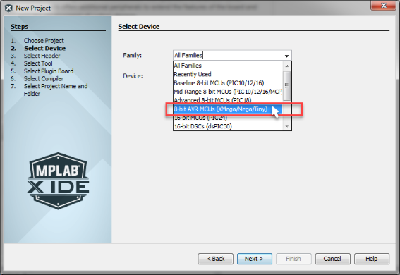
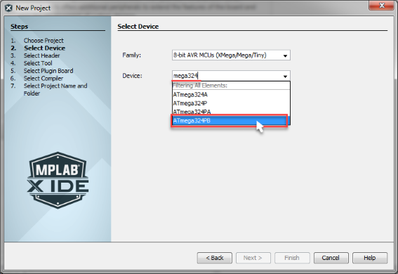
Select AVR from the MCU Families, or
search directly for the part number in the Device field.
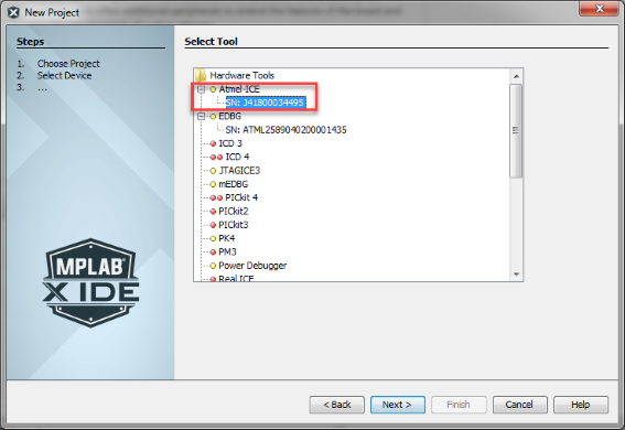
Select the hardware tool to associate with
the project.
Info: In Atmel Studio 7, this is done after
creating the project; but in MPLAB X IDE, this is part of the
project creation process.
Select
Toolchains.
Info: GCC projects are the default when new Projects are
created in Atmel Studio 7.
The project is given a name and location.
Attention: The Set as main project checkbox is selected
by default. The main project is the project associated with the
compile and debug options.
Writing some lines of AVR code
The first thing to do is add the AVR GCC main.c template to the
project.
This is done by right clicking on
Source Files, then selecting
main.c.
Name the file main, and click
Finish.
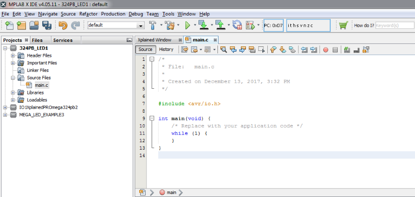
The project opens with the standard AVR GCC
main.c format, with an include to the AVR io.h header
file.
Info:AVR
io.h will add the relevant device header file to the
project, which in this case is a file called iom324pb.h. To
open this file, hover your cursor over a device register name, e.g.
DDRC (Data Direction Register C), and from the right-click menu
select Navigate > Go to
Declaration/Definition.
Which pin do we need to configure and how should it be configured,
in order to turn on the LED?
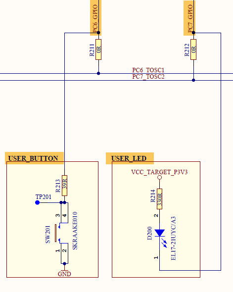
In order to answer this question, we need to check the ATmega324PB Xplained
Pro Schematic (as shown in an extract of the following schematic).
Info: USER_LED is connected to PC7: To turn on the LED,
PC7 should be set as an OUTPUT, LOW.
Info: USER_BUTTON is connected to PC6 and there is no
pull-up resistor. To read the switch status, PC6 should be set as an
input and internal pull-ups should be enabled.
How can PC7 be configured as an OUTPUT, LOW?
The datasheet is consulted to find an answer.
Info: If DDxn is written to ‘1’, Pxn is
configured as an output pin.
Info: If PORTxn is written logic zero, when the pin is an
output, the port pin is driven low.
DDRC7 should be written to
‘1’, while PORTC7 is set low.
The PORTC register is consulted below:
Tip: PORTC7 has a default value of ‘0’. So only DDRC7
needs to be set to ‘1’ to turn on the
LED.
How are AVR register bits set and cleared?
The code extract from the datasheet gives an example of
how to configure PORTx and DDRx register bits.
DDRC = (1<<DDRC7); will turn on the
USER_LED.
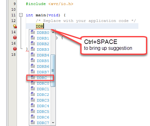
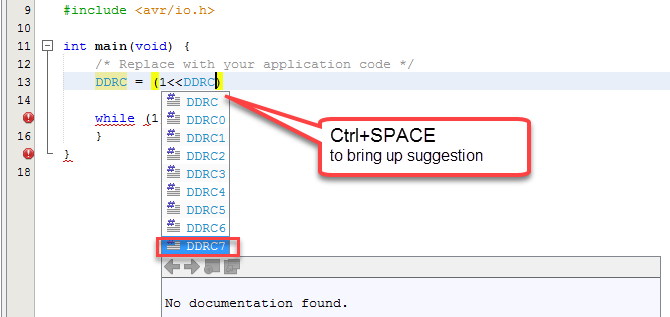
What help does the MPLAB X editor give to write AVR code?
Although the section above works through a first-principle bare-metal
approach to writing AVR code, there is also some help that the MPLAB X
Editor can give. The user can take advantage of the MPLAB X editor's
auto-complete functionality by typing Ctrl+SPACE,
as shown in the example below. The MPLAB X editor references the header
file for the ATmega324PB (iom324pb.h -> i/o map 324pb). Picking up
the correct name from the suggested options can prevent the user from
typing misspelled texts or undefined variable names, which is a typical
cause of compilation errors.
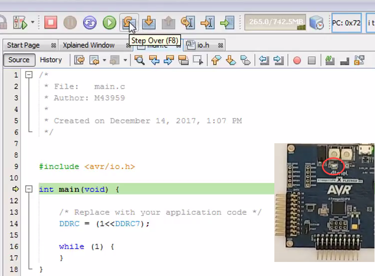
Verifying Functionality by Debugging
The functionality can simply be verified by debugging.
Click on the Debug Main
Projecticon.
This starts a debug session and runs the program. The LED should turn
on.
Info: This is equivalent to Start
Debugging, rather than Start Debugging and
Break.
Tip: Debugging should be
stopped at this point before proceeding to the next step. Single
stepping will not work when debug hits while(1).
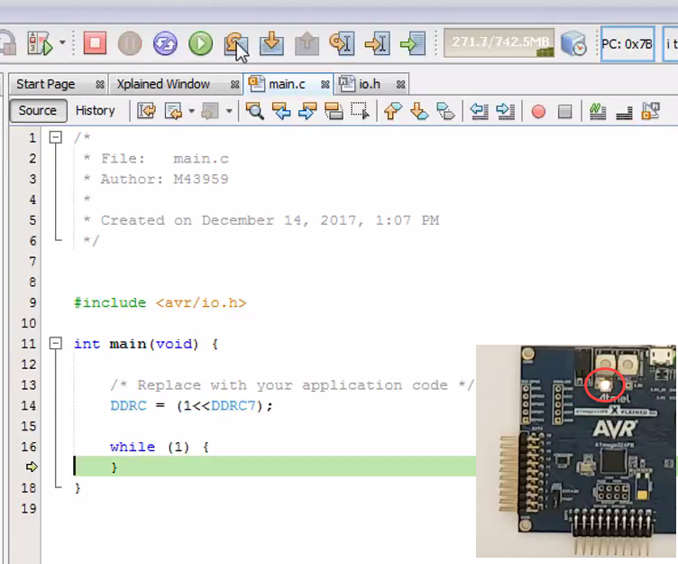
Also, a breakpoint should be added to demonstrate single stepping.
Without a breakpoint, Debug will run continuously. You can Pause and
then single step, but a breakpoint will stop where you
want.
By single stepping, the LED turns on as we
step over line 14: DDRC = (1<<DDRC7).
The online versions of the documents are provided as a courtesy. Verify all content and data in the device’s PDF documentation found on the device product page.


 Creating a new MPLAB X project for AVR
When the ATmega324PB Xplained Prokit is plugged into MPLAB X, a welcome page for the kit opens, with key links to find related technical information.
Creating a new MPLAB X project for AVR
When the ATmega324PB Xplained Prokit is plugged into MPLAB X, a welcome page for the kit opens, with key links to find related technical information.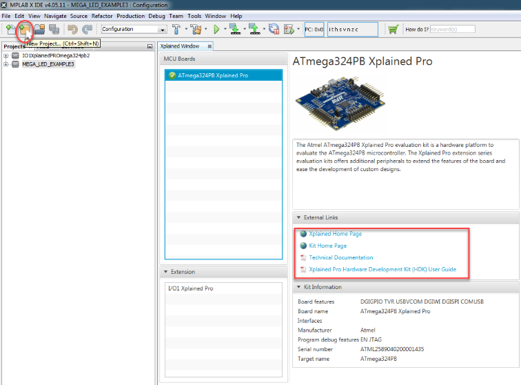
 .
. Select Standalone
Project
Info: This is equivalent to a GCC C Executable Project in Atmel Studio 7.
Select Standalone
Project
Info: This is equivalent to a GCC C Executable Project in Atmel Studio 7.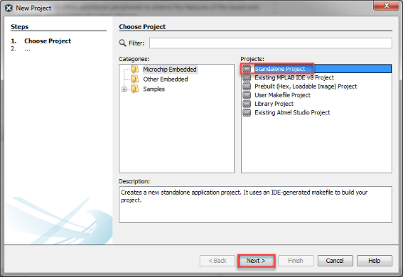
 Info: In Atmel Studio 7, this is done after creating the project; but in MPLAB X IDE, this is part of the project creation process.
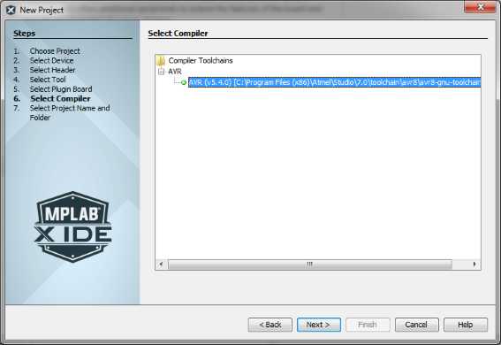 Info: GCC projects are the default when new Projects are created in Atmel Studio 7.
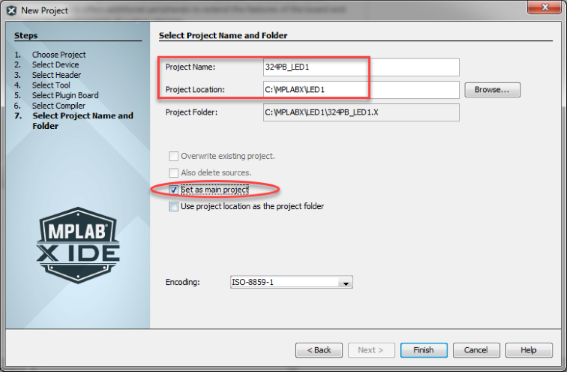 Attention: The Set as main project checkbox is selected by default. The main project is the project associated with the compile and debug options.
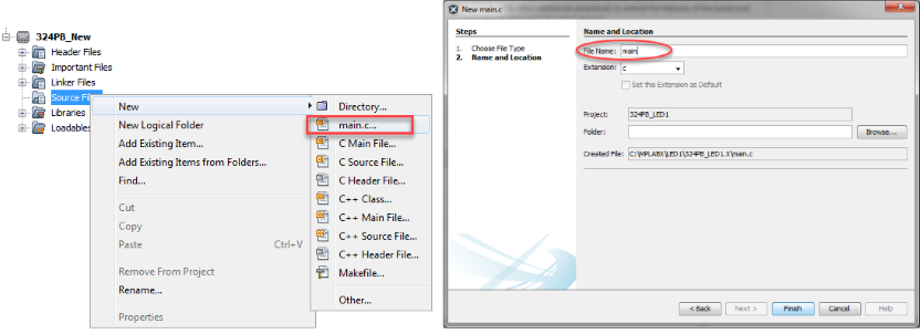
 Info: AVR io.h will add the relevant device header file to the project, which in this case is a file called iom324pb.h. To open this file, hover your cursor over a device register name, e.g. DDRC (Data Direction Register C), and from the right-click menu select Navigate > Go to Declaration/Definition.
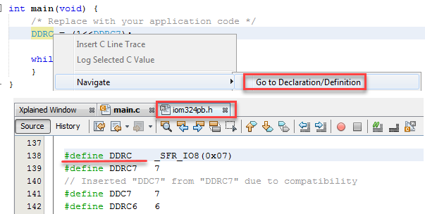
 Info: USER_LED is connected to PC7: To turn on the LED, PC7 should be set as an OUTPUT, LOW.Info: USER_BUTTON is connected to PC6 and there is no pull-up resistor. To read the switch status, PC6 should be set as an input and internal pull-ups should be enabled.
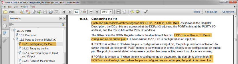 Info: If DDxn is written to ‘
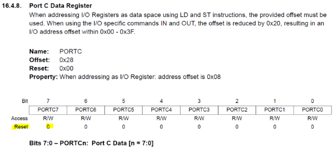 Tip: PORTC7 has a default value of ‘
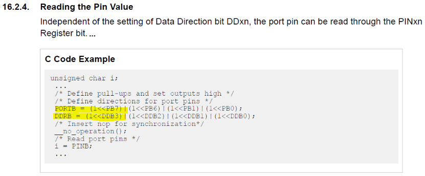

 icon.
This starts a debug session and runs the program. The LED should turn on.Info: This is equivalent to Start Debugging
icon.
This starts a debug session and runs the program. The LED should turn on.Info: This is equivalent to Start Debugging , rather than
  Start Debugging and
Break.Tip: Debugging should be stopped at this point before proceeding to the next step. Single stepping will not work when debug hits
Start Debugging and
Break.Tip: Debugging should be stopped at this point before proceeding to the next step. Single stepping will not work when debug hits