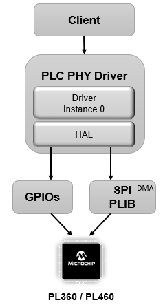
1.1.1.1 How the Library Works
The PLC PHY driver library is a single-client, single-instance based driver interface.
Abstraction Model
The PLC PHY library communicates with a PLC transceiver using an SPI port, Direct Memory Access and the GPIO controller.
The PLC transceiver performs PHY duties of the communication protocol, thus allowing a high latency attendance from the host MCU.
The PLC PHY library offers the necessary functions to control the transceiver, which include:
Library initialization.
Transmitting and Receiving PLC frames.
Accessing PLC Information Base (PIB) to get/set configuration parameters.
Enabling/Disabling transceiver Sleep Mode.
Check warnings due to Thermal Monitor control.
The client can be:
Application: Directly access the external PLC device (PL360/PL460) using the APIs provided by the PLC PHY Driver library.
PRIME / Meters And More PAL layer: Application can run a PLC communication stack (PRIME / Meters And More) by connecting it to the Platform Abstraction Layer (PAL) which can further be connected to the PLC PHY driver. In G3 stack, the PLC PAL is connected to G3-PLC MAC-RT driver instead of PLC PHY driver.

Driver Initialization and instance opening
First of all, driver has to be initialized by calling DRV_PLC_PHY_Initialize to get a valid handle.
Then, when an instance is opened by calling DRV_PLC_PHY_Open, the library loads a binary file onto the PLC transceiver. This is done using an internal transfer protocol through SPI port. After binary loading, the library manages the reset and startup of the transceiver. This task is transparent to the user, and the library is not available until binary file is transferred and thus PLC transceiver is ready to operate. At this point, the driver is ready to be configured and used. The status can be checked be calling DRV_PLC_PHY_Status.
PLC Transceiver Interrupt mapping
PLC transceiver events have to be notified to the MCU in which PLC PHY Driver is running. This is done using a physical connection between the transceiver and an interrupt-capable PIO in MCU.
The library implements DRV_PLC_PHY_ExternalInterruptHandler function, which is set as callback to be invoked when the interrupt is triggered on PIO. This function then reads information from the transceiver and performs the required operations.
Data Service Functions
PLC communication capabilities are provided by the following functions:
Frame Transmission. Frames are trasnmitted to PLC using DRV_PLC_PHY_TxRequest function.
Transmission result is reported by library through the configured callback function set on DRV_PLC_PHY_TxCfmCallbackRegister.
Frame reception is reported by library through the configured callback function set on DRV_PLC_PHY_DataIndCallbackRegister.
Management Functions
The PLC PHY library includes management functions to configure it and to retrieve information about the library, transceiver, and PLC medium status. Management functions include:
Information Base Access. There are several parameters at PHY level that can be written/read to change behaviour and get information to/from the library. In order to get/set these parameters, DRV_PLC_PHY_PIBGet and DRV_PLC_PHY_PIBSet functions are used. Available parameters are listed on DRV_PLC_PHY_ID Enum (G3-PLC), DRV_PLC_PHY_ID Enum (PRIME) and DRV_PLC_PHY_ID Enum (Meters And More).
PLC Transceiver Timer Referece. Every PLC transmission and reception timestamp is referenced to an interal 32-bit microseconds counter. The current value of such counter can be retrieved by PLC_ID_TIME_REF_ID using DRV_PLC_PHY_PIBGet.
PLC Transceiver Error handling. Errors in the PLC transceiver (here called "exceptions") are reported by the library invoking the callback function set in DRV_PLC_PHY_ExceptionCallbackRegister. Exceptions are described in DRV_PLC_PHY_EXCEPTION Enum.
PLC Transmission Enabling/Disabling. Sometimes it is required to inhibit the PHY driver to transmit frames to the PLC medium, but keeping everything else on the driver running and maintaining the Information Base. DRV_PLC_PHY_EnableTX function allow to enable/disable PLC transmissions using the TX Enable pin (PL460 only), keeping other driver mechanisms active, as well as its state machine. An application of this mechanism is the PLC PVDD monitor service, which monitors the PVDD voltage and when it is not in the expected range, PLC transmission is disabled to avoid PL460 damage; when the PVDD voltage is in the expected range, PLC transmission can be enabled again.
Sleep Mode. DRV_PLC_PHY_Sleep function allows entering/exitting PLC transceiver Sleep mode. In sleep mode, the PLC transceiver enters a low power mode. To exit from sleep mode it is not needed to load the PLC binary again. In case Sleep mode is exited, it is reported by the library by invoking the callback function set in DRV_PLC_PHY_SleepDisableCallbackRegister.
Working flow
The library's state machine is driven from the interrupt context and the tasks function (DRV_PLC_PHY_Tasks). Once an event is detected (Transmission Confirm or Receive Indication), a callback (if registered by the application) is given to the application from the tasks function.
The library does not support queuing of more than one transmission requests. The application must check and ensure that any previous request is completed before submitting a new one. This can be done by registering a Transmission Confirm callback function.
