
5.6.2.1 Zigbee Distributed Network Formation by Dimmable Light
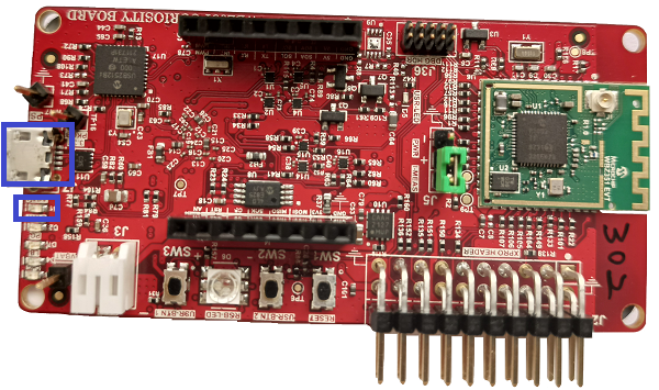
WBZ351 Curiosity Board
Devices (Device): | PIC32CX5109BZ31048(MCU) on WBZ351 module |
Peripherals (Used, On-Board): | User Button| UART-USB Converter|
Introduction
Though zigbee lights are Router device types, they have the capability of creating its own distributed network. Other routers and end-devices can enter into the network once it is formed. The demo steps explained here can be followed for any devices like color scene controller to get into the light formed distributed network.GitHub Repository
The firmware, .hex, and accompanying readme.md file
for the application can be found in the GitHub repository – dim_light_touch
Hardware Required
| Tool | Qty |
|---|---|
| WBZ351 Curiosity Boards | 1 |
| Micro USB cable | 1 |
| Personal Computer | 1 |
SDK Setup
Gettting Started with Software DevelopmentSoftware
TeraTermProgramming the precompiled hex file or Application Example
Programming the hex file using MPLABX IPE
-
Precompiled Hex file is located in "<Harmony Content Path>\wireless_apps_pic32cxbz3_wbz35\apps\zigbee\dim_light_touch" folder
-
Follow the steps mentioned here
Caution: Users should choose the correct Device and Tool information
Programming the Application using MPLABX IDE
-
Follow steps mentioned in of Running a Precompiled Example document
-
Open and program the Application Example "dim_light_touch.x" located in "<Harmony Content Path>\wireless_apps_pic32cxbz3_wbz35\apps\zigbee\dim_light_touch\firmware" using MPLABX IDE
<Harmony Content Path> how to find what is my Harmony Content Path
Demo Description
The demo applications demonstrates the Zigbee protocol functionality of PIC32CXBZ/WBZ family of devices and modules. It consists of a ZigBee 3.0 Coordinator and Router implemented as shown below :
| Application | Zigbee Logical Device Type | Functionality |
|---|---|---|
| Dimmable Light | Router | Is a lighting device that can form the distributed network. |
Demo Steps:
- Supply power to WBZ351 Curiosity Board consisting of Dimmbale Light
application by connecting a USB cable. Power Supply (PS) Green LED will turn on
when connect to PC.
- The application activity is shown
as "Console Log" through on board UART-USB converter
-
Open Terminal(eg: Tera Term) with the setup as shown below to look for these logs
-
On the PC side virtual COM port connection that corresponds to the board shall have following settings:
BAUD RATE: 115200 (as configured in SERCOM configuration)
PARITY: None
DATA BITS: 8
STOP BITS: 1
FLOW CONTROL: None
Distributed Network Formation with Light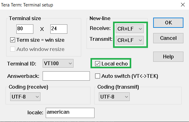
-
- Input command : resetToFN
-
If light device wouldn't be able to find any network to join, it will create a distributed network. Any device shall be able to join the network via appropriate authentication process. It will open up the network for other zigbee devices to join for first 180 seconds from the first powerON.
Shows the success console output from a Dimmable Light Application which is a Zigbee router and establishes a Distributed Network.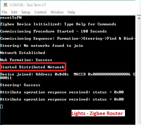
To open up the network after 180 seconds to allow other devices to join, we have to input the below commands in light, before commissioning is initiated in another device.
Input command: setPermitJoin 180 -> This command opens up the network for next 180seccommand: invokeCommissioning 8 0 -> This command opens up the network for "finding and binding procedure"
Creating Application Device Types From Scratch Using MCC
All the supported device types including this Dimmable light projects can be generated by following the steps in Generating project from MCC.