
7 Use Case Examples
Code snippets showing the implementation of basic operations of the LIN Responder Library
7.1 LIN Responder Use Case Examples
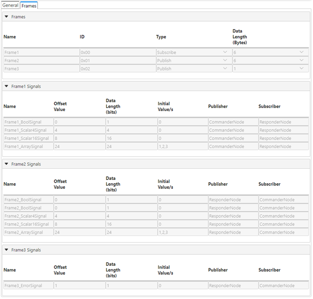
LIN_description_file;
LIN_protocol_version = "2.2";
LIN_language_version = "2.2";
LIN_speed = 9.6 kbps;

Nodes {
  Master: CommanderNode, 1 ms, 0 ms ;
  Slaves: ResponderNode ;
}

Signals {
  Frame1_BoolSignal: 1, 0, CommanderNode, ResponderNode ;
  Frame1_Scalar4Signal: 4, 0, CommanderNode, ResponderNode ;
  Frame1_Scalar16Signal: 16, 0, CommanderNode, ResponderNode ;
  Frame1_ArraySignal: 24, {1, 2, 3}, CommanderNode, ResponderNode ;
  Frame2_BoolSignal: 1, 0, ResponderNode, CommanderNode ;
  Frame2_Scalar4Signal: 4, 0, ResponderNode, CommanderNode ;
  Frame2_Scalar16Signal: 16, 0, ResponderNode, CommanderNode ;
  Frame2_ArraySignal: 24, {1, 2, 3}, ResponderNode, CommanderNode ;
  Frame3_ErrorSignal: 1, 0, ResponderNode, CommanderNode ;
}

Frames {
  Frame1: 0, CommanderNode, 6 {
    Frame1_BoolSignal, 0 ;
    Frame1_Scalar4Signal, 4 ;
    Frame1_Scalar16Signal, 8 ;
    Frame1_ArraySignal, 24 ;
  }
  Frame2: 1, ResponderNode, 6 {
    Frame2_BoolSignal, 0 ;
    Frame2_Scalar4Signal, 4 ;
    Frame2_Scalar16Signal, 8 ;
    Frame2_ArraySignal, 24 ;
  }
  Frame3: 2, ResponderNode, 1 {
    Frame3_ErrorSignal, 1 ;
  }
}

Node_attributes {
  ResponderNode{
    LIN_protocol = "2.0" ;
    configured_NAD = 0xFF ;
    product_id = 0x0, 0x0, 255 ;
    response_error = Frame3_ErrorSignal ;
    P2_min = 50 ms ;
    ST_min = 0 ms ;
    configurable_frames {
      Frame1 = 0xFFFF ;
      Frame2 = 0xFFFF ;
      Frame3 = 0xFFFF ;
    }
  }
}
Successful loading of the LDF in the LIN Responder GUI should display the following frames and signals in the Frames tab:
7.1.1 Reading and Writing Signals
The LIN Responder Library generates read and write APIs with static prototype based on
the defined signals in the UI. These APIs can be found in
lin_app.h.
7.1.1.1 Reading Signal Values
void App_ReadSignals(void)
{
    // Reading a boolean type signal
    bool boolSig;
    boolSig = l_bool_rd_Frame1_BoolSignal();

    // Reading an unsigned scalar signal of size 8 bits or less
    uint8_t scalarSig4;
    scalarSig4 = l_u8_rd_Frame1_Scalar4Signal();

    // Reading an unsigned scalar signal of size more than 8 bits but less than 16 bits
    uint16_t scalarSig16;
    scalarSig16 = l_u16_rd_Frame1_Scalar16Signal();

    // Reading a 3-byte array
    uint8_t rdData[3];
    l_bytes_rd_Frame1_ArraySignal(0, sizeof (rdData), rdData);
}
7.1.1.2 Writing Signal Values
void App_WriteSignals(void)
{
    // Writing value to a 3-byte array signal
    uint8_t wrData[] = {0x45, 0x32, 0x65};
    l_bytes_wr_Frame2_ArraySignal(0, sizeof (wrData), wrData);

    // Writing value to a boolean type signal
    l_bool_wr_Frame2_BoolSignal(1);

    // Writing value to a 4-bit scalar signal
    l_u8_wr_Frame2_Scalar4Signal(0x55);

    // Writing value to 16-bit scalar signal
    l_u16_wr_Frame2_Scalar16Signal(0xFFFF);
}
7.1.2 Frame Process and Error Callbacks
The following code snippets use GPIO toggling functions wherein a pin with custom name “LED0” is configured as a digital output in the Melody UI.
7.1.2.1 Assigning Frame Process Callbacks
The frame callback register functions are automatically generated based on the
user-configured frames in the UI. These callbacks are executed after the relevant frame
is successfully processed. Refer to lin_config.h for the frame callback register APIs.
The following code shows an example of assigning LED toggle callback functions for Frame1 and Frame2. This will set LED0 high for a duration of 10s after successful processing of Frame1 while 15s for Frame2.
#include "mcc_generated_files/system/system.h"

void LED_Toggle10ms(void);
void LED_Toggle15ms(void);

int main(void)
{
    SYSTEM_Initialize();
    // Enable the Global Interrupts for PIC.
    INTERRUPT_GlobalInterruptEnable();
    // Enable the Peripheral Interrupts for PIC devices with peripheral interrupt enable function.
    INTERRUPT_PeripheralInterruptEnable();

    // Assign frame process callbacks.
    FRAME1_AppCallbackRegister(LED_Toggle10ms);
    FRAME2_AppCallbackRegister(LED_Toggle15ms);

    while(1)
    {
        LINRESP_Handler(); // Remove for non-blocking mode
    }
}

void LED_Toggle10ms(void)
{
    LED0_SetHigh();
    __delay_us(10);
    LED0_SetLow();
}

void LED_Toggle15ms(void)
{
    LED0_SetHigh();
    __delay_us(15);
    LED0_SetLow();
}
7.1.2.2 Assigning Error Callbacks
The Melody-generated error callback register functions allow the user to implement
custom error handlers. An error callback is executed after the relevant error is
detected. Refer to lin_responder.h for the error callback register
APIs.
The following code shows an example of assigning LED toggle callback for readback and response too short errors. This will set LED0 high for a duration of 10s when a readback error is detected and 15s for a response too short condition.
A readback error is flagged when the transmitted response byte is not equal to the data read from the responder’s RX pin. A response too short error, on the other hand, is detected when the response received is shorter than expected.
#include "mcc_generated_files/system/system.h"

void LED_Toggle10ms(void);
void LED_Toggle15ms(void);

int main(void)
{
    SYSTEM_Initialize();
    // Enable the Global Interrupts for PIC.
    INTERRUPT_GlobalInterruptEnable();
    // Enable the Peripheral Interrupts for PIC devices with peripheral interrupt enable function.
    INTERRUPT_PeripheralInterruptEnable();

    // Assign a callback for readback error.
    LINRESP_ReadbackErrCallbackRegister(LED_Toggle10ms);

    // Assign a callback for response too short error.
    LINRESP_ShortRespErrCallbackRegister(LED_Toggle15ms);

    while(1)
    {
        LINRESP_Handler(); // Remove for non-blocking mode
    }
}

void LED_Toggle10ms(void)
{
    LED0_SetHigh();
    __delay_us(10);
    LED0_SetLow();
}

void LED_Toggle15ms(void)
{
    LED0_SetHigh();
    __delay_us(15);
    LED0_SetLow();
}