1.5.1 MCC Project Configuration
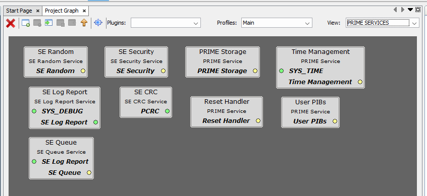
The following figure shows the MCC project graph of PRIME Base Modem application for PIC32CXMTG-EK.

- Since it is an hybrid project, both PLC PHY and RF215 drivers are present. For PLC-only or RF-only projects, only one of them is needed.
- The PLC PVDD Monitor service is needed to monitor the PVDD voltage of PL460 in order to disable PLC transmission in case the voltage is not in the expected range, to avoid PL460 damage. If the PVDD voltage is in the expected range, the PLC transmission is enabled.
- The PLC PHY Coupling service is needed to configure the PLC transmission parameters for the selected transmission coupling branch.
- The USI service is needed to send/receive messages through serial interface (UART/USB) to/from external device.
- The Console system service is used to output information messages from Application and Log Report service.
- The Time system service is required by both PLC PHY and RF215 drivers. It is used for timer control on PRIME Stack and Application (blink periodically the status LED).
- The TRNG peripheral library is used by the Random service to generate random numbers, which is needed by the PRIME Stack. It is not mandatory due to the Random service can generate random numbers without it. However, if the used MCU has a TRNG peripheral, it is recommended to use it.
- Crypto_v4 and wolfCrypt libraries are used by the Security service to perform cryptographic operations needed by the PRIME Stack.
- The PRIME STACK folder contains all the components needed by the PRIME Stack:

- The PRIME SERVICES folder inside contains all the services needed by the PRIME Stack, except the Firmware Upgrade service, which needs to be in the root view due to its connection to the Memory driver. These services are always needed by the PRIME Stack.
The following figure shows the MCC configuration of the PRIME Stack.

- PRIME mode: It must be set to BN
- PRIME version: Configured to 1.4 to have PLC and RF capabilities. It can be set to 1.3.6 depending on the Base Node Modem application.

- Since it is an hybrid project, both PLC PHY and RF PHY interfaces are enabled. For PLC-only or RF-only projects, only one of them is needed. In a v1.3.6 project, it is possible to enable the Serial PHY interface, too.
For additional information about configuration of the PRIME Stack, the PRIME PAL and the PRIME Services, refer to the corresponding documentation.
PIC32CXMTG-EK Board Component
This Component defines the board capabilities.


Digital Interface
Green and Blue LEDs are selected, so corresponding PIOs are named and configured accordingly.
USB Debugger Interface
- Console System Service
- Flexcom0 Peripheral Library
Figure 1-58. Console Configuration 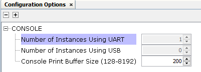
Figure 1-59. Flexcom0 Configuration 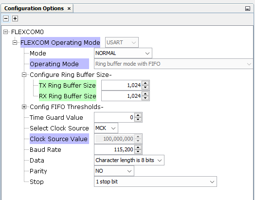
Note that buffer sizes are increased manually for this application.
All related PIOs are automatically configured.
Xplained Pro Interface
PL460 Evaluation Kit at PHY level is selected to be connected to the Xplained Connector.
- PLC PHY Driver
- Flexcom5 Peripheral Library
- ADC Peripheral Library
Figure 1-60. PLC PHY Configuration 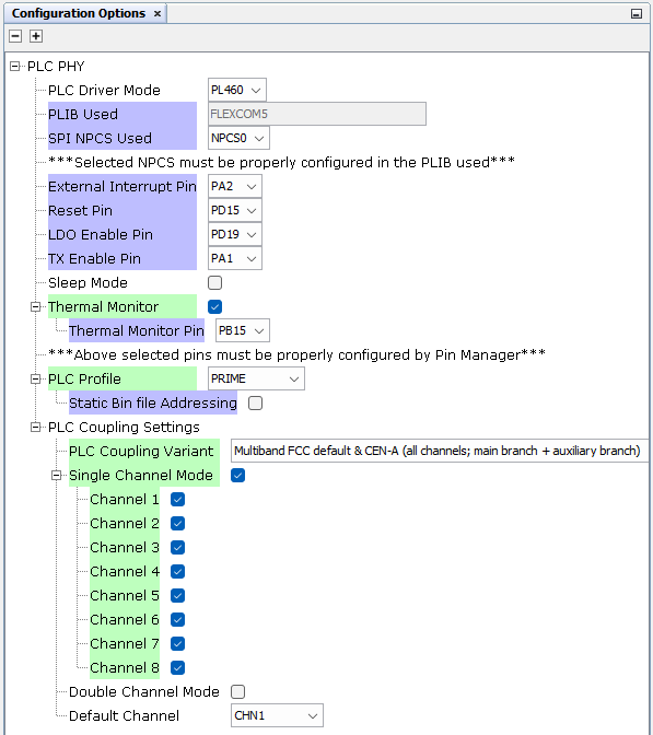
Note that Thermal Monitor is manually enabled, and PRIME profile selected for this application.
The PLC Coupling variant uses the default coupling stage of the evaluation kit (Multiband FCC + CENELEC-A for the PL460-EK). If other PLC band configuration is required, it can be easily modified.
Figure 1-61. Flexcom5 Configuration 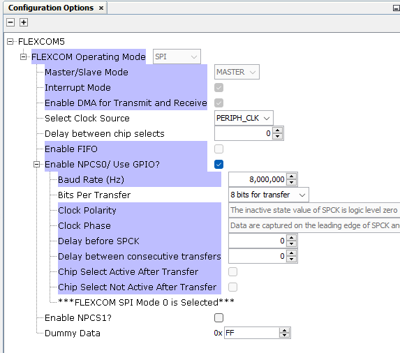
Figure 1-62. ADC Configuration 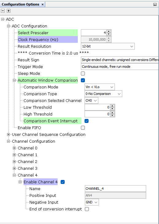
Note that Prescaler and Automatic Window Comparison are manually configured. For Comparison, only the Event Interrupt has to be enabled, the rest of parameters will be overwritten by the PVDD Monitor after initialization, so provided values in this configurator are not used.
All related PIOs are automatically configured.
Note that the PLC PHY Coupling Component and the PLC PVDD Monitor Component are not automatically added by the Board Component. They have been added to the project manually.
Additional Components
- Harmony Core Service
- TRNG Peripheral Library
- TIME System Service
- TC0 Peripheral Library
connected to TIME Service and configured as shown in the following
figure:
Figure 1-63. TC0 Configuration 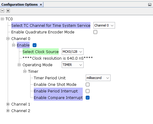
- USI Service configured as
shown in the following figure:
Figure 1-64. USI Configuration 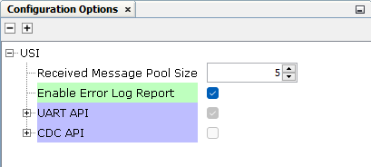
- Flexcom7 Peripheral Library connected to USI Service and configured by default
- PLC PVDD Monitor Service
connected to ADC Peripheral Library and configured as shown in the following
figure:
Figure 1-65. PVDD Monitor Configuration 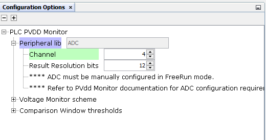
- PLC PHY Coupling automatically configured by the PLC PHY Driver
- Memory Driver connected to SEFC0 and automatically configured by the Firmware Upgrade Service
- RF215 Driver configured as
shown in the following figure:
Figure 1-66. RF215 Configuration 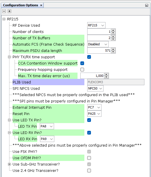 In the pin configuration, configure the RF pins (all other pins are auto-configured by the SHD component):
Figure 1-67. RF215 Pin Configuration 
- Flexcom3 Peripheral Library connected to RF215 Driver and automatically configured by it
- Crypto_v4 and wolfCrypt
Library, configured as shown in the following figure:
Figure 1-68. wolfCrypt Library Configuration 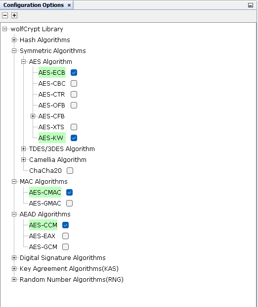
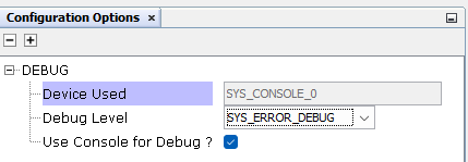
- Debug System Service
connected to the Console System Service and configured as shown in the
following figure:
Figure 1-69. Debug Configuration