
1 Introduction
Microchip offers an FPGA-based MIPI CSI-2 transmit reference solution with PolarFire® and PolarFire SoC FPGAs. It is transceiver-enabled, which upgrades our GPIO-based IP solution to support data rates of up to 2.5 Gbps/lane and facilitate 4K video data. It complements our MIPI CSI-2 receiver IP and is part of our extensive Smart Embedded Vision Portfolio of IPs and a popular choice for vision applications at the edge.
The MIPI Transmit FMC Card works with the PolarFire® Video and Imaging Kit and PolarFire SoC Video Kit.
| Description | Quantity |
|---|---|
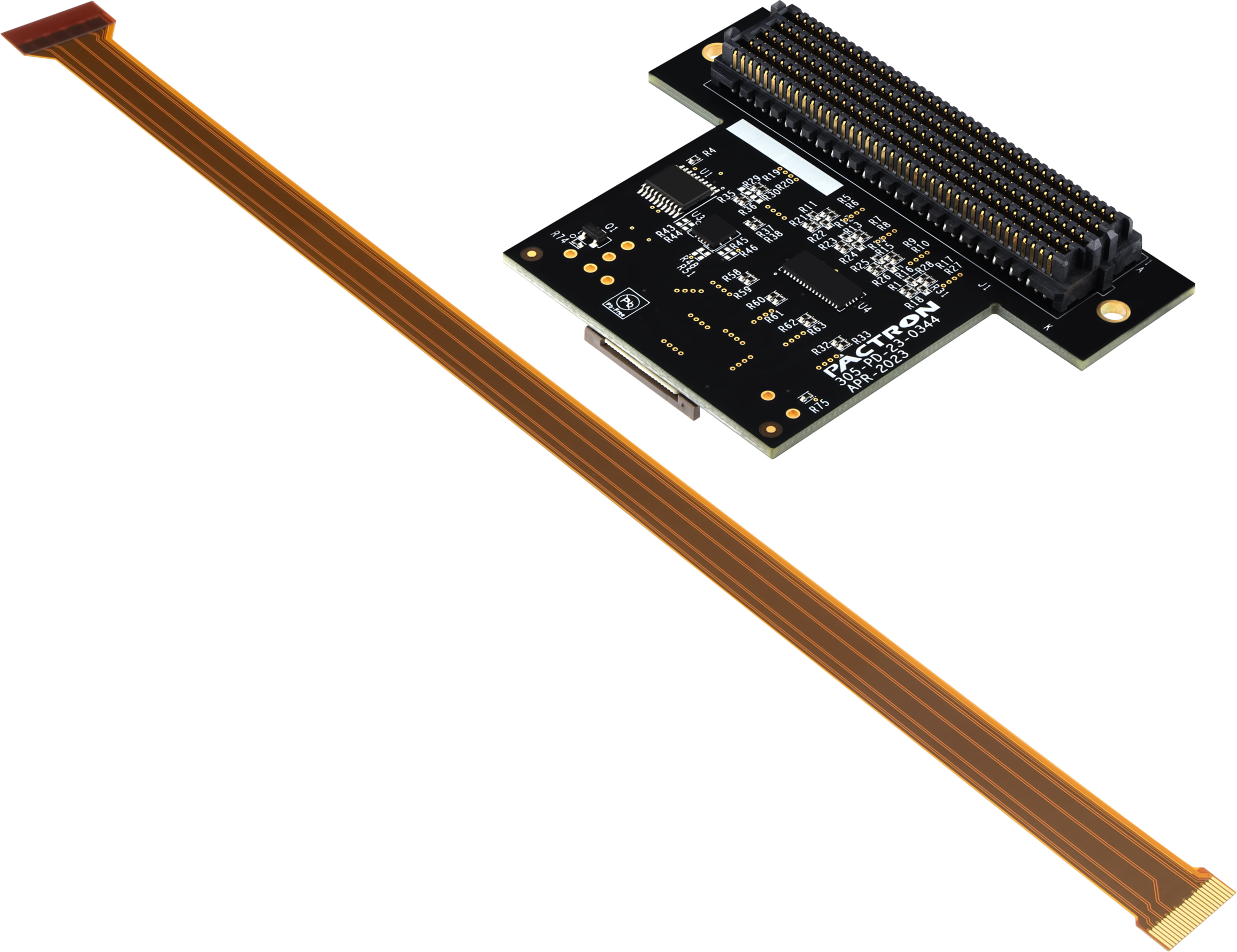
| MIPI TX FMC daughter board | 1 |
| Quickstart Card | 1 |
| Flexible Printed Circuit (FPC) Cable, 200 mm: 22 to 15 Pin | 1 |
1.1 Hardware Features
The MIPI TX FMC daughter card supports the following hardware features:
- D-PHY 2.5 Gbps
- Nine GPIOs
- 4 × Transceivers
1.2 Demo Requirements
| Requirement | Description |
|---|---|
| Hardware | |
| PolarFire® video kit | MPF300-VIDEO-KIT-NS kit contents:
|
| MIPITx FMC daughter card | VIDEO-DC-MIPITX |
| MIPI cable | MIPI 22 to 15-pin cable |
| Raspberry Pi | Raspberry Pi 4 model B |
| USB keyboard and mouse | USB keyboard and mouse as input devices for Raspberry Pi |
| 5V power pack/AC adapter | Power adapter with type C cable that supports 5V/3A, or as per RPi’s minimum requirements |
| SD card | SD card (16 GB or 0) of any class |
| Micro HDMIcable | Micro HDMI to HDMI type to connect to monitor to Raspberry Pi |
| HDMI monitor | To connect Raspberry Pi Micro HDMI (port 0 or port 1) to HDMI of monitor |
| Software | |
| Linux® | Ubuntu v20.4 For more details about running the demo, see Raspberry Pi SD Card Setup and Run section. |
| Libero® SoC Design Suite | FlashPro Express is installed as part of Libero SoC Design Suite version 12.0 or later releases. |
1.3 Demo Setup
Before you begin with demo, ensure to download the following files from AN5494: MIPI CSI-2 Transmitter:
- mpf_an5494_v2024p1_jb - Job file to test on Raspberry Pi
- mipi_csi2_tx_using_rpi.zip - Raspberry Pi image file
Demo setup comprises two parts:
- Setting up the hardware
- Programming the device
1.3.1 Setting up the Hardware
Setting up the hardware involves verifying the jumper settings and interfacing the MIPI Transmit FMC (VIDEO-DC-MIPITX) card with the PolarFire video kit, along with the MIPI cable.


The following table lists the jumper and switch settings of PolarFire video kit.
| Jumper and Switch | Position | Description |
|---|---|---|
| J15 | Open | SPI Target and Initiator mode selection. By default, select SPI Initiator |
| J14 | MIPI Transmit FMC | MIPI Transmit FMC to be connected |
| J17 | Open | 100K PD for TRSTn |
| J19 | Pin 1 and 2 | Default: XCVR_VREF is connected to ground |
| J28 | Pin 1 and 2 | Default: Programming through the FTDI |
| J6 | Pin 1 and 3 | Default: VDDAUX4 voltage is set to 2.5V |
| J25 | Pin 9 and 10 | Bank4 voltage |
| J36 | Pin 1 and 2 | Default: Board power-up through the SW4 |
| SW4 | OFF or ON | Power On or Off slide switch |
| J20 | 12 Volts Input | 12V input to the board |
| J12 | USB-UART | USB-UART mini cable |
For setting up the hardware, perform the following steps:
- Ensure that the preceding jumper settings in table are set on the video kit. For more details, see Figure 1-2.
- Connect the MIPI TX daughter card to J14 of the FMC connector of the PolarFire video kit, see Figure 1-2.
- Connect the ribbon cable between the MIPI Transmit FMC card and the Raspberry Pi J3 camera connector (see Figure 1-3).
- Connect the host PC and the video kit through J12 of the video kit using the USB mini cable.
- Connect the 12V power supply cable to the J20 on board DC jack of the video kit.
Power-up the board using the SW4 slide switch.
Connect the 5V power supply cable to the USB type C Power In socket of the Raspberry Pi.
Connect the USB keyboard and USB mouse to the Raspberry Pi.
- Power-up the Raspberry Pi and HDMI monitor. (Raspberry Pi splash screen on the HDMI monitor appears.)
- After the power-up, program the PolarFire Video Kit device. For more information, see the Programming the PolarFire Device section.
- After programming the PolarFire device, the Raspberry Pi SD card setup needs to be done, and the test pattern generator starts streaming the video data as seen in when running the demo, see Raspberry Pi SD Card Setup and Run section.
1.3.2 Programming the PolarFire Device
This section describes how to program the PolarFire Video Kit device with the job file
using FlashPro Express. The job file mpf_an5494_v2024p1_jb to test on
Raspberry Pi is provided in the AN5494: MIPI CSI-2 Transmitter.
- On the host PC, start the FlashPro Express software from its installation directory.
- To create a new job project on the Project menu, click New or New Job Project from FlashPro Express Job.
- In the New Job Project
from FlashPro Express Job dialog box, perform the following
steps:
- Programming job file: Click Browse and navigate to the location where the job file is located and select the file.
- FlashPro Express job project location: Select Browse and navigate to the location where you want to save the project.
- Click OK. The required programming file is selected and ready to be programmed in the device. The FlashPro Express window appears.
- Verify that a programmer number appears in the Programmer box. If it does not, verify the board connections and click Refresh/Rescan Programmers.
- To program the device, click RUN. When the device is programmed successfully, a RUN PASSED status is displayed.
- To close FlashPro Express, click .
1.4 Setting up the Demo
The following sections describe the demo set up and run process.
1.4.1 Setting up the Raspberry Pi 4
For setting up Raspberry Pi 4, perform the following steps:
- Connect the HDMI monitor to the HDMI0 port of the Raspberry Pi.
-
Connect the ribbon cable between the MIPI Transmit FMC card and the Raspberry Pi J3 camera connector as shown in the Fig 1.3
- Connect the 5V power supply cable to the USB type C Power In socket of the Raspberry Pi 4 Model B.
- Connect the USB keyboard and USB mouse to the Raspberry Pi 4 Model B.
- Power-up the Raspberry Pi 4 Model B
and HDMI monitor.
Raspberry Pi SD card setup needs to be done. For information about the steps related to setup, see Raspberry Pi SD Card Setup and Run section.
1.4.2 Raspberry Pi SD Card Setup and Run
The following steps and associated commands are necessary to enable the Raspberry Pi to detect the PolarFire-based MIPI TX as a camera source.
- Download and extract the
mipi_csi2_tx_using_rpi.zipto getmipi_csi2_tx_using_rpi_v1.imgfile. - Download and install rpi-imager from raspberry pi website based on your Operating System (OS), that is, Windows® or Linux®.
- Insert SD card (atleast 16 GB) to the host system. The host system can be either windows or Linux which runs the rpi-imager.
- Run rpi-manager and perform the
following steps:
- Click on CHOOSE OS under Operating System field and then select the option Use custom. Navigate and select the extracted raspberry pi image mentioned in step1.
- Click on CHOOSE STORAGE under Storage field and select SD card that is inserted to the system.
- To start writing image to the SD card, click on WRITE. This process may take 15 to 20 min.
- Insert SD card in the Raspberry Pi SD card slot.
- Power on Raspberry Pi and login once Raspberry Pi boots.
This section describes the following commands that must be run on a Raspberry Pi.
- Open Ubuntu terminal.
- To view the kernal release number, enter
uname -rcommand.The output appears as
kernal release:
                        6.1.20v71+
. - Issue the following V4L2 command to
configure and wait for CSI data reception.
v4L2-ctl
                            --device=/dev/video0
                            --set-fmt-video=width=1920,height=1080,pixelformat=RGGB --stream-mmap
                            --stream-to=test.raw --stream-count=1
Note: If the command is stuck and does not finish executing, it means data reception is not working.- Do not stop or kill the command. While the command is running, restart PolarFire device using SW4 switch and check if data is received. If data not received even after restarting the board at least ten times, recheck the ribbon cable connection (given that every step is followed correctly.)
- If the command returns with
the "<" symbol, it means data reception is successful.Note: Before power cycling the video kit, "<" may appear. It is acceptable.
- Issue the following command
to stream the data live from the PolarFire video kit board.
sudo ffplay -f video4linux2 -input_format bayer_rggb8 -i /dev/video0 - Another window appears with the test pattern from the video kit. For more details, see MIPI CSI-2 Transmitter Validation section.
1.4.2.1 MIPI CSI-2 Transmitter Validation
Output Pattern 1:
The following figure shows the output pattern of the MIPI CSI-2 Transmitter with transceiver for a data rate of 800 Mbps/Lane for Full HD resolution at 30 FPS (1920 x 1080 at 30 FPS) and uses a 2 lane MIPI configuration is tested with the Raspberry Pi 4 model B.
Output Pattern 2:
The following figure shows the output pattern of the MIPI CSI-2 Transmitter for 2.5 Gbps per lane with XCVR tested with the MIPI Introspect Analyzer (SV3C – DPRX 4-Lane D-PHY Analyzer).