3 External Amplifier
Some motor control development boards (see Table ) are equipped with Operational Amplifiers to amplify the motor phase currents and DC bus current (external Op Amp configuration). To obtain information on amplifier gain, see the user’s guide of the specific development board.
The external amplifier outputs from the development board and the internal amplifier outputs of the dsPIC® DSC are connected to a single analog channel on the DIM.
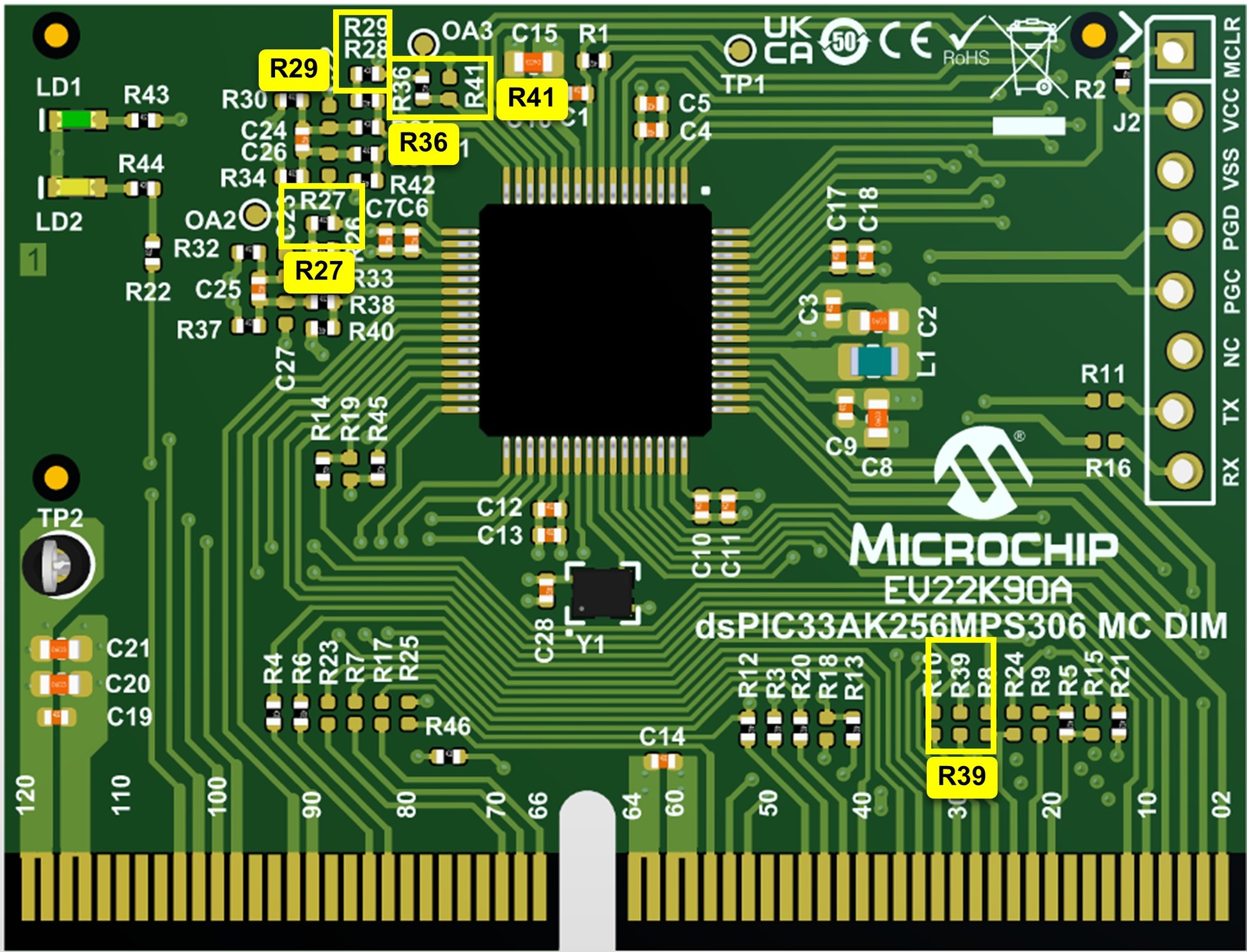
The DIM is configured to use the internal amplifier outputs of the dsPIC® DSC by default. Table 3-1 summarizes the jumper resistors to be populated and removed to convert the DIM from “internal Op Amp configuration” to “external Op Amp configuration” or vice versa.
| Operational Amplifier | Jumper Resistor (0R) Settings on the DIM | Firmware Setting | |||||
|---|---|---|---|---|---|---|---|
| Internal Amplifier Configuration (default) | External Amplifier Configuration | ||||||
| Populate | Remove | Populate | Remove | ||||
| OA2 | R27 | R39 | R39 | R27 |
| ||
| OA3 | R29, R36 | R41 | R41 | R29, R36 | |||