9.1.1 Example code for 8-bit PIC MCUs
If you want to run example code in the MPLAB X IDE simulator, the IDE's UART IO feature,
available for most devices, allows you to view output from the stdout
stream. Once properly configured, the output of printf() and other
functions writing to stdout can then be viewed from the IDE when the
program is run in the simulator.
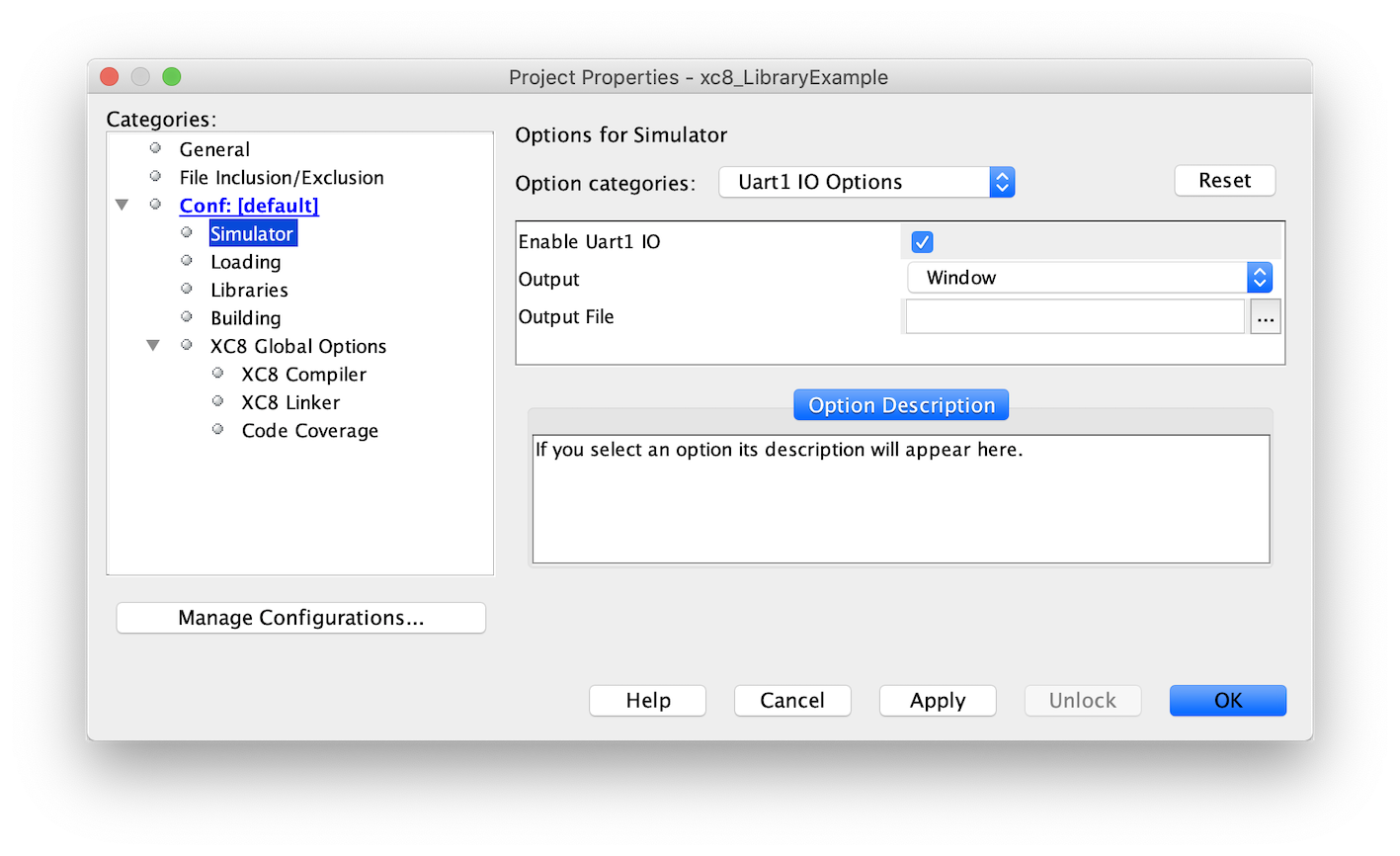
When available, this feature is enabled using the Enable Uartx IO checkbox in the Project properties > Simulator > Uartx IO Options dialog (shown below). You might have a choice of UARTs. Choose the UART that your code will write to. Output can be displayed in a window in the IDE or sent to a file on your host machine, based on the selections you make in the dialog.

The UART initialization and print-byte functions generated by the MCC can be used by the
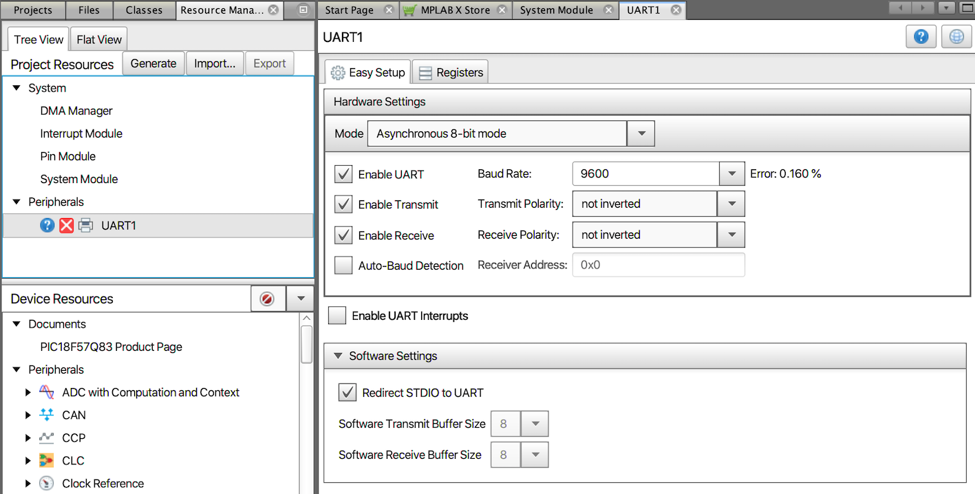
simulator. If you enable the Redirect STDIO to UART checkbox in
the UARTx pane (in the lower part of the pane shown below), MCC
will ensure that the print-byte function used by printf() calls the
MCC-generated function that sends data to the UART. The default communication settings
should work in the simulator, but these may need to be changed if the UART is to be used
on hardware.

The same UART IO feature allows you to read input from the stdin stream.
Once properly configured, scanf() and other functions reading from
stdin can then take input from a file when the program is run in
the simulator.
If you want to run example code that uses scanf() in the MPLAB X IDE
simulator, you will need to set up a UART, as above. You can use the same UART for input
as you do for output using printf(). Additionally, provide the input
characters to the program by creating and adding to your project an empty file, using a
suitable extension, such as .txt. Open this file in the editor and add
the characters that you want to send to the program inside quotes, e.g. "here is
my input" Commands that control how the input should be read can also be
added to this file, as described in the MPLAB® X IDE User’s
Guide.
Next, open the Window > Simulator > Stimulus dialog. Select
the Register Injection tab. Start typing the name of the receive
register used by the USART in the Reg/Var field to see a pop-up
list of matching register names. This register name will vary from device to device.
Refer to your device data sheet, although you can often look to see the name of the
register being returned by the UARTx_Read() function created by
MCC. Ensure the Trigger field is set to
Message, and the Format field is set
to Pkt. In the Data Filename field, enter
the name and path of the text file that contains your input. Finally, ensure that the
stimulus has been applied by clicking the circular green button at the top left and
checking the message shown at the bottom of the dialog. This button toggles the
application of the stimulus.
The following image shows the stimulus correctly set up for the UART1 on a PIC18 device that uses a receive register called U1RXB.

With the stimulus correct configured, scanf() and other functions
reading from stdin will take input from the file specified.
