2 Getting Started
Getting started resources for the PIC18F56Q24 Curiosity Nano board in the MPLAB Tools Ecosystem.
2.1 Getting Started Now with PIC®

- Examples: MPLAB Discover is a tool to help you find Microchip example projects. It offers several ways to filter projects so that you can efficiently find a Microchip-tested example, as close as possible to your application requirements, to use as a starting point for your development.
-
Configure: MCC Melody provides Libraries, Drivers, and Peripheral Libraries (PLIB) for the development of embedded software for a range of supported Microchip MCUs, which are configured using MPLAB® Code Configurator (MCC).
- Develop: MPLAB X IDE (Integrated Development Environment), which is available for Windows, Linux and macOS, also MPLAB® XC C Compilers.
- Debug: With the MPLAB X IDE and/or the MPLAB Data Visualizer, the PIC18F56Q24 device on the PIC18F56Q24 Curiosity Nano board is programmed and debugged by the on-board debugger. Therefore, no external programmer or debugger tool is required.
- Boards: The PIC18F56Q24 Curiosity Nano board is a supported part of the Curiosity Nano Development
Platform, which includes the Curiosity Nano Base for Click
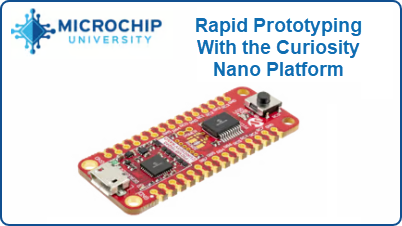
Boards™. Tip: Have a look at this free Microchip University course.
2.2 How the Curiosity Nano Fits Into the MPLAB Tools Ecosystem
2.2.1 MPLAB X IDE Support for Curiosity Nano
When the board connects to the computer for the first time, the operating system will install the driver software. The drivers for the board are included with MPLAB® X IDE. Once this is done, when connecting the Curiosity Nano to a host PC via USB, if MPLAB X IDE is open, a Kit Window is opened with several key links for that Curiosity Nano.
When creating a new project, the part number on the Curiosity Nano will be detected, as will the debug tool.

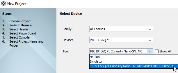
- For the PIC18F56Q24 Curiosity Nano board, use MPLAB® X IDE version 6.15, device family pack “PIC18F-Q_DFP” version 1.23.425, and tool pack “nEDBG_TP” version 1.13.715 or newer
- The latest device family packs are available through in MPLAB® X IDE or online at Microchip MPLAB® X Packs Repository. For more information on packs and how to upgrade them, refer to the MPLAB® X IDE User’s guide - Work with Device Packs.
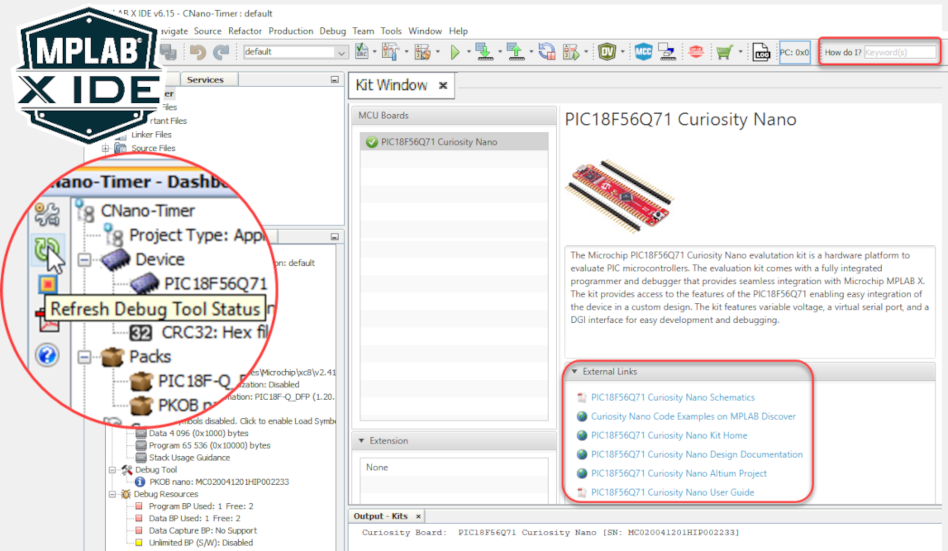
- If closed, reopen the Kit Window in MPLAB® X IDE through the menu bar
- The 'How do I?' search bar often gives excellent results if you're new to MPLAB X IDE
- 'Debug main project" will start a debug session
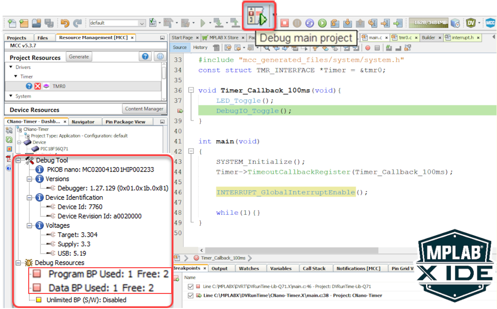
- After clicking on 'Refresh Debug Tool Status,' you can see information such as MCU Target Voltage
- What are Program- and Data-Break Points? MPLAB X IDE Advanced Debugging - Breakpoints Demo
- Reference for example above - MCC Melody Timer0 Driver: 100 ms Timer, API Ref Code
2.3 MPLAB Data Visualizer Support for Curiosity Nano
The Curiosity Nano, via a USB/serial bridge, facilitates a connection between a UART on the Target MCU and your computer's COM port. For example, you may use this to connect to the MPLAB Data Visualizer or other terminal programs.
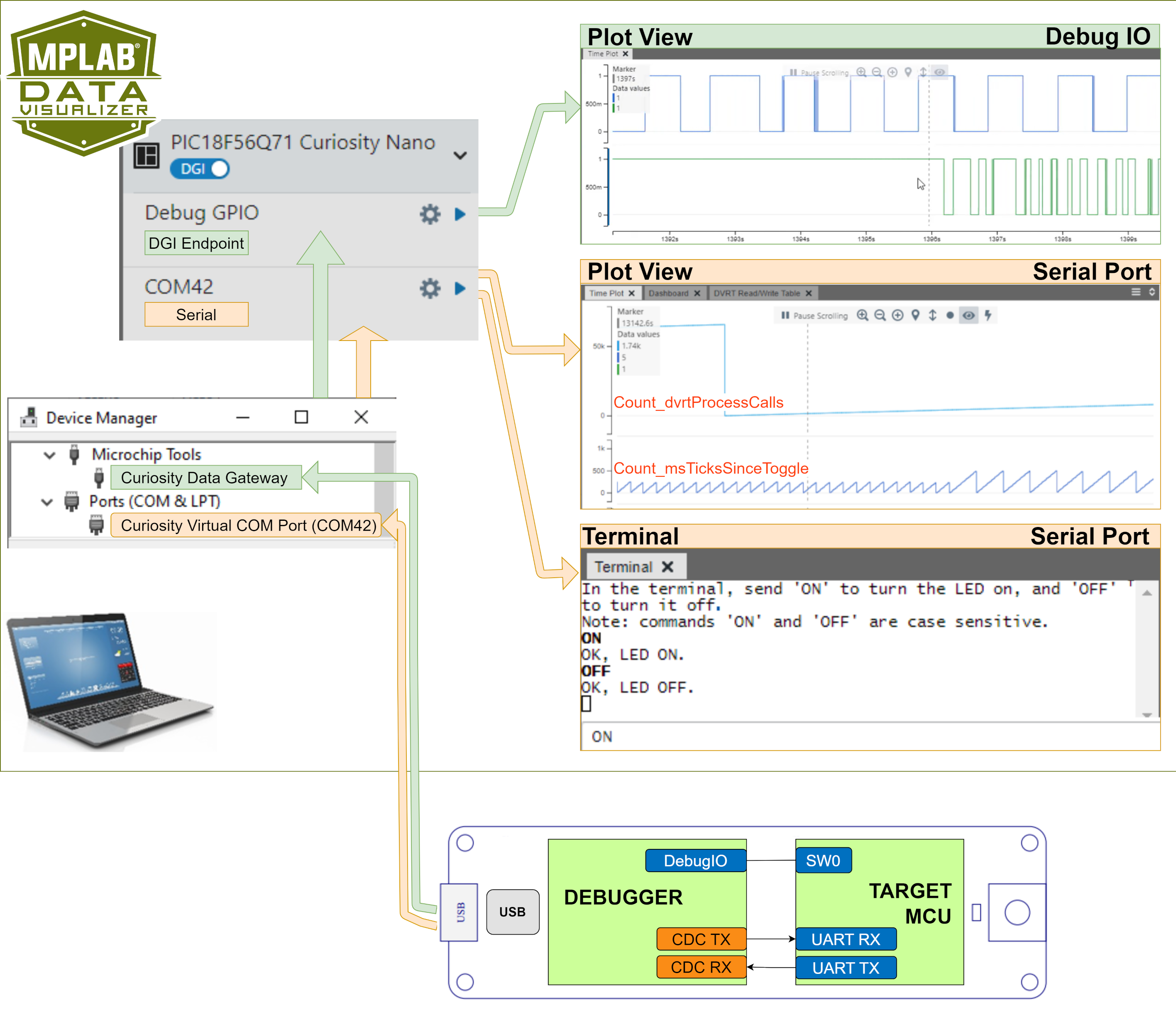
- Plot View - DebugIO: DebugIO Hello World (Microchip University).
- Plot View - Serial Port: MCC Melody Use Case Data Visualizer Run Time Use Case 1.
- Terminal - Serial Port: MCC Melody UART Driver: LED Control Commands.
2.4 Using Pin-Headers
The edge connector footprint on the PIC18F56Q24 Curiosity Nano has a staggered design where each hole is shifted 8 mil (~0.2 mm) off-center. The hole shift allows regular 100 mil pin headers to be used without soldering on the board. The pin-headers can be used in applications like pin sockets and prototyping boards without issues once they are firmly in place.
- Start at one end of the pin-header and gradually insert the header along the length of the board. Once all the pins are in place, use a flat surface to push them in.
- For applications using the pin-headers permanently, it is still recommended to solder them in place
- Once the pin-headers are in place, they are hard to remove by hand. Use a set of pliers and carefully remove the pin-headers to avoid damage to the pin-headers and PCB.

