
1.2 Board Configuration
TA100 8-Pin SOIC Socket Board Jumper Configurations
- SPI Connections: J3, J4, J5, J6 and J7 in position closest to socket (white band labeled with SPI)(1)
- I2C Connections: J3, J4, J5, J6 and J7 in position furthest from socket (white band labeled with I2C)(1)
- 3.3V Power: J10 with shunt across 3V3 and PWR positions(2)
- 5.0V Power: J10 with shunt across 5V and PWR positions(2)
Note:
- Jumpers J3, J4, J5, J6 and J7 must all be set with position pins 1 and 2 shorted (SPI) or all set with position pins 2 and 3 shorted (I2C) for proper operation in a given interface mode.
- The I/O levels of the GPIO, SPI and I2C signals will track with the supply voltage.
| SPI Configuration | I2C Configuration |
|---|---|
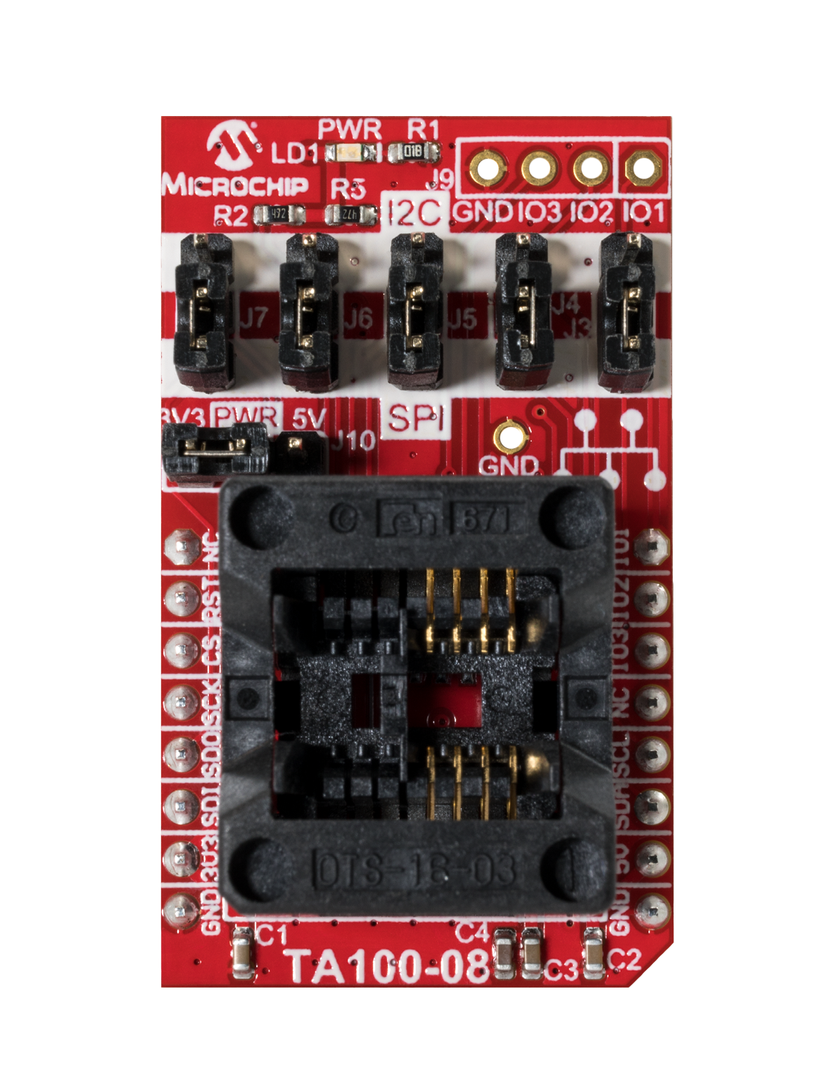 | 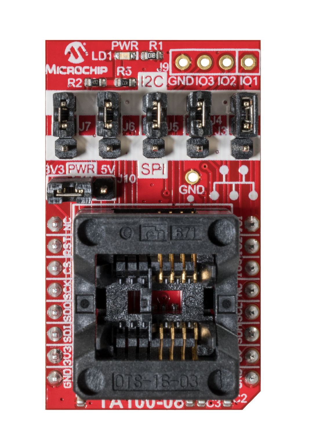 |