1 Module Documentation
1.1 16-bit Bootloader:Application Home Page
- 16-Bit Bootloader:Application Overview
-
An overview of the bootloader:application infrastructure.
- Application Verification
-
The Application Verification describes the different methods used to verify the application binary before the bootloader executes the application binary.
- Merging Bootloader and Application Hex Files For Production
-
How to merge the Bootloader and Application hex files into a single hex file for production.
1.2 User Interface
-
Configure the memory space settings to match the ones defined in the original bootloader project. This includes the start address of the application and the start address of the Application Remapped Interrupt Table.
-
Verify that the configuration bits of the application match the bootloader.
-
Copy the interrupt settings over from the bootloader so the application project knows which interrupts will use the independent interrupt vectors and which will use the default settings. In addition it will define and place the interrupt vectors are the correct location in the Remapped Interrupt Vector Table.
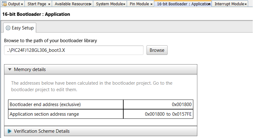
The 16-bit Bootloader: Application Builder screen is shown below. Much of the data on this form is pulled from the bootloader configuration and is automatically used in the application to ensure they match. This includes the memory map, interrupt configuration and chip configuration data from the bootloader project. The user needs to browse to the location of the bootloader project being used. Once selected, MCC will go to the directory within the selected project containing the contract file that the application builder should use. Once the project file is loaded, the application builder will use it to set the memory addresses and check to make sure the current project has the same configuration settings and interrupt sources. If it finds a conflict it will display what the conflicts which needs to be fixed.
If a verification method was selected in the bootloader that requires input data from the application developer, some additional fields might appear for the required data. For more information about these verification fields, Refer to the section that corresponds to the verification method in use.
Over the life of the project, the user may have changed some of the configuration bits by updating different modules. These setting will now be in conflict with the ones in the bootloader. This will be an issue when the user switches to booting the device using the bootloader instead of the configuration bits in this standalone project. So it's highly recommended that this screen be opened during the development of the project and at the end the of the project. When the user re-visits this MCC screen, it will re-verify the configuration settings in this standalone project with the configuration settings in the bootloader. If a difference is found, the user has two options. Either revert the changes in the application to match the bootloader or go back to the bootloader and change the settings there to match the application. While some configuration bits can be overridden at run time, it can be an extremely difficult procedure if it's even possible since most config settings can not be over-ridden at run time.
The MCC Bootloader:Application builder below is responsible for importing the memory map and other settings from the bootloader project and using them to configure the bootloader features of the application FW. It does this by asking the user for the location of the bootloader project. After entering the location of the project, MCC will scan the project directory for the memory map, the interrupt configuration, and chip configuration settings. It will then apply those settings to the application project. This includes moving the location of the application to the application space defined in the bootloader.
Also during this time the MCC will compare the bootloader and application configuration bits for each project. If they are not the same it will prompt the user with the values that are different and ask the user to change them. It's imperative that the configuration bits match between the bootloader and application projects. They they don't then the user will see random failures in their code.
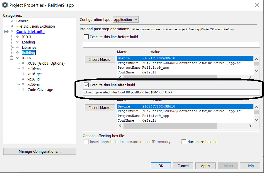
If the bootloader is required to do any type of verification of the application image other than application being non-blank, the bootloader will need to compute the application's CRC/Checksum/ECDSA signature and compare the computed value against the expected value stored in the application image. The expected signature of the application is calculated and inserted into the application's hex file by running the PostBuild.bat script as the last part of the application build process. The user will need to add the command below to run this script to the post build step in the application's project file. The instructions to do this are included in every application project that MCC builds and are listed below along with a picture of application project settings dialog.
-
Right click on your project, and click 'Properties'.
-
Select the 'Building' left navigation node.
-
Check the box next to 'Execute this line after the build'.
-
In the text field below,
-
add "cd mcc_generated_files/boot && postBuild.bat $(MP_CC_DIR) $(ProjectDir) $(ImageDir) $(ImageName)" (without quotes) if you are on a Windows machine.
-
add "cd mcc_generated_files/boot && ./postBuild.sh $(MP_CC_DIR) $(ProjectDir) $(ImageDir) $(ImageName)" (without quotes) if you are on a Linux/Unix/Mac machine.
-
Merging Bootloader and Application Hex Files For Production
How to merge the Bootloader and Application hex files into a single hex file for production.
For all other help, go to the 16-bit Bootloader: Bootloader help section.
1.3 Application Verification
1.3.1 Application Verification Overview
Before the bootloader launches an application, it can verify that there is a valid application image loaded into memory. This verification takes many different forms. This section discusses each of the various verification methods implemented in this bootloader solution, how each works, and some of the engineering considerations when selecting a verification method. Refer to each sub-section for the discussion of each verification method.
The overall flow could look something like this:
The verification method in use is selected using the drop-down menu provided in the Bootloader : Bootloader configuration window. The method in use is transferred to the target application project so it can generate the required application header for verification.
There is an application image application header that is placed at the start of each application image. For some verification methods this might be 0 bytes (no data added). Other verification methods might require several fields in order to verify the application image. Refer to verification method's sub-topic to review that methods application header format.
There are two main API that are used regardless of the verification method in use:
|
Function |
Description | |
|---|---|---|
|
bool BOOT_Verify(void) |
Returns true if the image was verified based on the verification method selected during the bootloader configuration. Returns false if the image is not present or invalid. | |
|
void BOOT_StartApplication(void) |
This function transfers control from the bootloader to the application. Care should be taken to tear down the bootloader resources to their default state before calling this function. This includes, but is not limited to, interrupts and peripherals. Once this function is called the application code will start to run. |
If the bootloader is required to do any type of verification of the application image other than application being non-blank, the bootloader will need to compute the application's CRC/Checksum/ECDSA signature and compare against the expected value stored in the application image. The expected signature of the application is calculated and inserted into the application's hex file by running the PostBuild.bat script as the last part of the application build process. The user will need to add the command to run this script to the post build step in the application's project file. The instructions to do this are included in every application project that MCC builds and are listed below along with a picture of application project settings dialog.
-
Right click on your project, and click 'Properties'.
-
Select the 'Building' left navigation node.
-
Check the box next to 'Execute this line after the build'.
-
In the text field below,
-
add "cd mcc_generated_files/boot && postBuild.bat $(MP_CC_DIR) $(ProjectDir) $(ImageDir) $(ImageName)" (without quotes) if you are on a Windows machine.
-
add "cd mcc_generated_files/boot && ./postBuild.sh $(MP_CC_DIR) $(ProjectDir) $(ImageDir) $(ImageName)" (without quotes) if you are on a Linux/Unix/Mac machine.
-

1.3.2 Bootloader Application Verification Method - Not Blank
In the "Not Blank" verification method, the bootloader will verify that the application image space is completely unprogrammed. This does not check the validity of the application image. It only verifies that something has been programmed into the application space. It does not check for any types of errors in flash memory.
This form of verification is very quick and results in very fast entry to the application from the bootloader. It does not provide any error detection capability. It can't detect if an invalid firmware image was loaded or if the memory has corrupted since being programmed.
In the implementation provided only the application reset address is checked to make sure that it is not still in the erased state.
To strengthen this verification a bit more, the Unified Bootloader Host Application (UBHA) software package was updated for the 16-bit devices to program this address last of all the program memory. This way if a firmware image is partially loaded but gets interrupted before it completes, the reset address will not be programmed and the bootloader will refuse to jump to the application. If a new host application is created for use with this firmware and this verification method is used, it is suggested that a similar approach is implemented.
1.3.3 Bootloader Application Verification Method - Checksum16
Overview
In the "Checksum" verification method, a 16-bit checksum is calculated over a user specified range of memory addresses and is compared to a signature value stored in memory. If the calculated checksum value matches the stored checksum value, the application is allowed to launch.
This form of verification is decent at detecting errors in communication and if the memory has been accidentally erased/overwritten. A checksum is good at detecting gross errors and even down to single bit errors. A checksum is not able to protect very well against intentional manipulation of the memory by an attacker. A checksum verification is also rather quick to calculate allowing the application to be verified and launched rather quickly.
- Implementation Details
-
Memory Formating and Addressing
16-bit devices have 3 bytes of instruction address per every 2 PC addresses. A 4th "phantom" byte is added with a 0x00 value. Below is an example of what the memory might look like:PC Address
Opcode
Operation
0x1000
0x0007FFDF
rcall 0x14AE
0x1002
0x00060000
return
Note the 0x00 that precedes each of the opcodes. This is the phantom byte. This doesn't actually exist in memory but is returned when a read of the memory is done of the instruction from firmware. Also note that between the two example instructions, the PC address only incremented by 2 addresses. With only 2 PC addresses for every 4 bytes, not every byte is addressable.
Since not every byte is addressable directly either a new addressing scheme has to be used (as is done in the .hex files) or limitations have to be put on the addressability of the memory. This implementation was chosen to keep the addresses so they match the hardware PC addresses. This implementation is thus limited to only allowing checksums on complete instructions (all 4 bytes, including the phantom byte). Thus odd addresses are not allowed. All checksums must be calculated on full instructions.
The example calculation of the 2 instructions above would look like the following:
Checksum = 0xFFDF + 0x0007 + 0x0000 + 0x0006 = 0xFFEC
Application Image Header
The bootloader needs a known good value against which to compare the calculated checksum. A application image header is created at the start of the application image that stores all of the information required to verify the application image. For this implementation, the format of the Application Image Header is as follows:
Offset
Length
Item
Description
0
2
Checksum
The expected 16-bit checksum value of the application image
2
4
Checksum Start Address
The PC instruction address where the checksum should start. It is highly recommended that this is the start address point to itself so that everything after the checksum is included in the checksum, including the "Checksum Start Address" field itself. This address is configured in the application image so that an application can selectively decide to exclude some memory for checking for data that might not be common across all devices (e.g. - calibration data, serial numbers, emulated EEPROM, etc.)
6
4
Checksum End Address
The last PC instruction included in the checksum. Every byte of the instruction addressed in this field will be included in the checksum, including the phantom byte. This address is configured in the application image so that an application can selectively decide to exclude some memory for checking for data that might not be common across all devices (e.g. - calibration data, serial numbers, emulated EEPROM, etc.)
So if a device has a valid application memory partition from 0x3000-0x7FFF inclusive, then this is what the application image header might look like on that device:Address
Length
Item
Value
0x3000
2
Checksum
(Calculated - e.g. 0x41FB)
0x3002
4
Checksum Start Address
0x00003002
0x3006
4
Checksum End Address
0x7FFE (last PC instruction address in memory range to be checked).
0x300A
0x4FF6
Firmware Image
Firmware Image Opcodes
A few key items to note from this example:-
The checksum start address can not include the checksum.
-
The checksum start address is recommended to include itself (thus set to 0x3002 in this example).
-
The checksum end address is the last valid PC instruction address in the memory (0x7FFE is the last valid instruction address in the application memory range).
-
1.3.4 Bootloader Application Verification Method - CRC32
Overview
In the CRC32 verification method, a 32-bit CRC-32Q signature is calculated over a user specified range of memory addresses and is compared to a signature value stored in a application image header at the start of the application image. If the calculated signature matches the signature stored in the application image header, the application is allowed to launch.This form of verification is good at detecting errors or if the memory has been accidentally erased/overwritten and good at detecting gross errors and even down to single bit errors. A CRC is not able to protect very well against intentional manipulation of the memory by an attacker. A CRC verification is not nearly as quick as a checksum, but provides better protection. It is faster than a hash algorithm, but less secure in terms of memory protection.
- Implementation Details
-
Memory Formating and Addressing
16-bit devices have 3 bytes of instruction address per every 2 PC addresses. A 4th "phantom" byte is added with a 0x00 value. Below is an example of what the memory might look like:PC Address
Opcode
Operation
0x1000
0x0007FFDF
rcall 0x14AE
0x1002
0x00060000
return
Note the 0x00 that pre each of the opcodes. This is the phantom byte. This doesn't actually exist in memory but is returned when a read of the memory is done of the instruction from firmware. Also note that between the two example instructions, the PC address only incremented by 2 addresses. With only 2 PC addresses for every 4 bytes, not every byte is addressable.
Since not every byte is addressable directly either a new addressing scheme has to be used (as is done in the .hex files) or limitations have to be put on the addressability of the memory. This implementation has chosen to keep the addresses so they match the hardware PC addresses. This implementation is thus limited to only allowing CRC calculations on complete instructions (all 4 bytes, including the phantom byte). Thus odd addresses are not allowed.
Application Image Header
The bootloader needs a known good value against which to compare the calculated CRC value. A application image header is created towards the start of the application image that stores all of the information required to verify the application image. Notice that these address may include the computed CRC32 itself. To avoid the obvious issue here of including the computed CRC32 in the signature space, when computing or verifying the CRC32 the values of these located will be zero during the computation or of the CRC32. For this implementation, the format of the application image header is as follows:Offset
Length
Item
Description
0
4
CRC value
The expected 32-bit CRC value of the application image
4
4
Start Address
The first PC instruction included in the CRC calcuation. It is highly recommended that this is the start address point to itself so that it is included in the calculation. This address is configured in the application image so that an application can selectively decide to exclude some memory for checking for data that might not be common across all devices (e.g. - calibration data, serial numbers, emulated EEPROM, etc.)
8
4
End Address
The last PC instruction included in the CRC calculation. Every byte of the instruction addressed in this field will be included in the CRC calculation, including the phantom byte. This address is configured in the application image so that an application can selectively decide to exclude some memory for checking for data that might not be common across all devices (e.g. - calibration data, serial numbers, emulated EEPROM, etc.)
So if a device has a valid application memory partition from 0x3000-0x7FFF inclusive, then this is what the application image header might look like on that device:Address
Length
Item
Value
0x3000
4
CRC-32Q signature value
(Calculated - e.g. 0x41FB310D)
0x3004
4
Start Address - first address to be checked. Recommended to include itself (but not the signature) so 0x3004 in this example.
0x00003004
0x3008
4
End Address
0x7FFE (last PC instruction address in memory range to be checked).
The application firmware image then immediately follows the application image header.
A few key items to note from this example:-
The CRC start address can not include the CRC.
-
The CRC start address is recommended to include itself (thus set to 0x3004 in this example).
-
The CRC end address is the last valid PC instruction address in the memory (0x7FFE is the last valid instruction address in the application memory range).
-
1.3.5 Bootloader Application Verification Method - SHA-256
Overview
In the SHA-256 verification method, a hash is calculated over a user specified range of memory addresses and is compared to a signature value stored in memory. If the calculated hash value matches the stored hash value, the application is allowed to launch.
This form of verification is very good at detecting any change in the data. The SHA-256 calculation is very computationally intensive and can take quite a long time depending on the amount of data being processed. This verification scheme is suggested only on parts running at rather high speeds (70MIPS+). At slower speeds (like 16MIPS of the PIC24F products), this computation on an entire device memory could take several seconds. The current implementation requires approximately 150 cycles per byte of program memory checked. So a 128KB part running 100MIPS would take around 200ms to verify using this method. A 128KB part running at 16MIPS would take 1.1 seconds to verify.
Implementation Details
Memory Formatting and Addressing
16-bit devices have 3 bytes of instruction address per every 2 PC addresses. A 4th "phantom" byte is added with a 0x00 value. Below is an example of what the memory might look like:|
PC Address |
Opcode |
Operation | |
|---|---|---|---|
|
0x1000 |
0x0007FFDF |
rcall 0x14AE | |
|
0x1002 |
0x00060000 |
return |
Note the 0x00 that precedes each of the opcodes. This is the phantom byte. This doesn't actually exist in memory but is returned when a read of the memory is done of the instruction from firmware. Also note that between the two example instructions, the PC address is only incremented by 2 addresses. With only 2 PC addresses for every 4 bytes, not every byte is addressable.
Since not every byte is addressable directly either a new addressing scheme has to be used (as is done in the .hex files) or limitations have to be put on the addressability of the memory. This implementation has chosen to keep the addresses so they match the hardware PC addresses. This implementation is thus limited to only allowing hashes on complete instructions (all 4 bytes, including the phantom byte). Thus odd addresses are not allowed. All hashes must be calculated on full instructions.
Application Image Header
The bootloader needs a known good value against which to compare the calculated hash. An application image header is created at the start of the application image that stores all of the information required to verify the application image. For this implementation, the format of the application image header is as follows:|
Offset |
Length |
Item |
Description | |
|---|---|---|---|---|
|
0 |
32 |
Hash |
The expected SHA-256 hash value of the application image (32 bytes). This data is stored using only the lower 16-bits of each instruction. The 4th byte of every instruction is a phantom byte and can't be used for data storage and using just the 3rd byte makes the code to process/store the hash more complex, thus only the lower 16-bits of each instruction are used. | |
|
32 |
4 |
Start Address |
The PC instruction address where the hash should start. It is recommended that the start address points to the first byte of information after the hash value such that even the "Start Address" field is included in the hash. This address is configured in the application image so that an application can selectively decide to exclude some memory for checking for data that might not be common across all devices (e.g. - calibration data, serial numbers, emulated EEPROM, etc.) | |
|
36 |
4 |
End Address |
The last PC instruction included in the hash. Every byte of the instruction addressed in this field will be included in the hash, including the phantom byte. This address is configured in the application image so that an application can selectively decide to exclude some memory for checking for data that might not be common across all devices (e.g. - calibration data, serial numbers, emulated EEPROM, etc.) |
|
Address |
Length |
Item |
Value | |
|---|---|---|---|---|
|
0x3000 |
32 |
Hash |
(Calculated - e.g. 0x41FB45F204381DEFCA204829619FCA34DBEEE982125792FA4E6091E1EAB3E160) | |
|
0x3020 |
4 |
Start Address |
0x00003020 - The first address to be checked in the hash. It is recommended that the start address points to itself, 0x00003020 in this example. | |
|
0x3024 |
4 |
End Address |
0x00007FFE (last PC instruction address in memory range to be checked). |
This would be immediately followed by the firmware image of the application.
-
The start address cannot include the hash.
-
The start address is recommended to include itself (thus set to 0x3020 in this example).
-
The end address is the last valid PC instruction address in the memory (0x7FFE is the last valid instruction address in the application memory range).
1.3.6 Bootloader Application Verification Method - ECDSA
To verify that the application image has not been tampered with and that the application image comes from the expected source, ECDSA signing is often used. The details of this process is beyond the scope of this document and here will just focus on the execution details. ECDSA verification requires the generation of a ECDSA Private/Public key pair, adding the public key and verification code to the bootloader source and having the application project use the private key to sign the final application hex file and finally using all of this information to generate a pass/fail after the application has been verified. This diverse set of operations also requires an equally diverse set of tools and scripts. The bootloader MCC module will setup this infrastructure for the user to enable a quick development time and also provide example scripts for the more expert user.
Overview
The specific details of the ECDSA verification process is beyond the scope of this document. For this project we use the Microchip's ATECC608 device to speed up the ECDSA verification of the image. While the ECDSA verification can be done purely in software, doing it on 100Mhz CPU will take about 1 second. This same verification using the ATECC608 takes about 10ms. The ECDSA verification uses the 3 pieces of information below to verify that the application image is valid and comes from the expected source.
-
The ECDSA signature stored in the application image header.
-
The public key stored in the bootloader
-
The SHA256 or SHA384 hash of the application computed by the bootloader.
The ATECC608 takes these three pieces of information and computes a pass/fail result which is then used by the bootloader to determine if it should allow control of the system to be passed to the application code.
NOTE: SHA384 hashing and the p384 curve are currently only supported in Trust Anchor devices such as the TA100.
ECDSA Flow
Below shows the basic user flow to build both the bootloader and the application. The basic flow is the same bootloader flow that is described in the bootloader documentation doc_how_to_build_a_bootloader. But in this case we will also need to generate public/private keys and enable communication to the ATECC608.
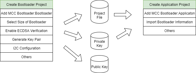
Bootloader Generation
The user starts by first creating a project for the device and adding the MCC module for 16-bit bootloader:bootloader to the project as described here doc_how_to_build_a_bootloader. During this process the verification method is selected and is shown below. The picture may vary depending on the device selected and its capabilities and is discussed in details in the bootloader section doc_how_to_build_a_bootloader. For ECDSA verification, the user must select ECSDA Verification from the Verification Scheme drop down box shown below.
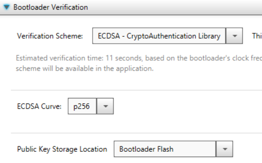
Once ECDSA Verification has been chosen, the user will be prompted to select the curve type and where the public key is stored or if the user wants to just generate a matching set of Private/Public keys as shown below. For this example, the keys will be auto generated. Pressing "Generate Example Key Pair Files" will prompt the user where to store the generated keys. This information will also be stored and used by the MCC Bootloader:Application later on.

ATECC608 I2C Interrupt Selection.
It's mandatory that one of the two following I2C interrupt modes are chosen and configured by the user. If the user does not, communication with the ATECC608 will fail.
- Polling Mode
-
By default, the PIC24/dsPIC controller communicates with the ATECC608 using a I2C driver with interrupts enabled even though interrupts are not mandatory. Unfortunately, some PIC24/dsPIC devices and bootloader configurations have only a single interrupt table and the interrupts may not be shareable between bootloader and application. Other PIC24/dsPIC devices and configurations have two independent interrupt tables and do not need to share the interrupt. If this device/configuration only supports a single interrupt table and the user wants the I2C interrupt used in the application, the user will need to disable the I2C interrupts for the bootloader. To do this, the user will disable the I2C interrupts in the MCC->System->Interrupt Module as shown below. By doing this, the bootloader I2C driver generated will operate in a pure polling mode and for those devices/configurations that have only a single interrupt table, it would allow the application to use the I2C interrupts.
Figure 1-4. Disabling I2C Interrupts 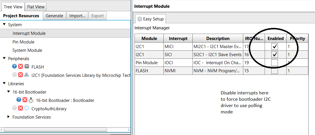
- Interrupt Mode
-
If the user wants to use I2C interrupts in the bootloader, depending on the device/configuration the user needs to inform the bootloader driver that the I2C interrupts need to be sent to the bootloader and not the application. If redirection is required, the user will see a Interrupt Vector Table Remapping window shown below. In this window, the user needs to move the Master/Slave I2C interrupts for the device they are using from "Remap to Application" -> "Keep In Bootloader". If the user does not see the Interrupt Vector Table Remapping window below, that means the device/configuration supports dual interrupt tables and interrupts are shareable between Bootloader mode and Application mode.
Figure 1-5. Interrupt Selection Screen 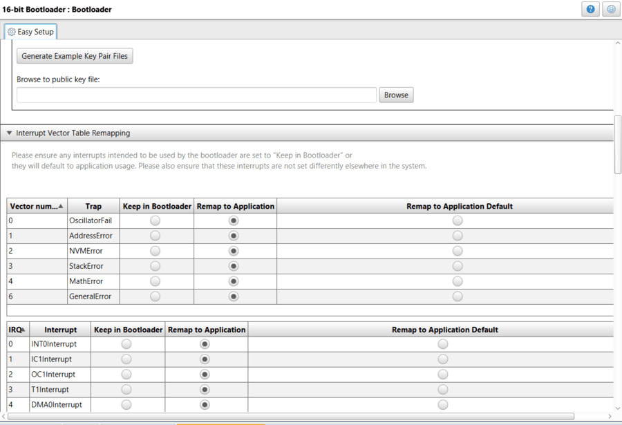
- Compiler/Linker Settings
-
To limit the size of the code the user may need to update the compiler/linker settings shown below. To access both of these settings at the same time, select Project->XC16 and select "Isolate each function in a section" and "Removed unused sections". Select both of these shown below. If this is not done the bootloader code will still function but will require 2K-3K more program space and the user will get a large number of linker errors until either the below options are selected or the bootloader size is increased.
Figure 1-6. Updating Compiler Settings 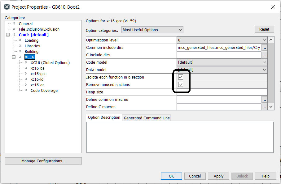
- Generating the bootloader
-
At this point, the user can generate the bootloader using the instructions found at doc_how_to_build_a_bootloader
- Adding ECDSA Verification to the Application
-
Once the bootloader has been built, building the application is quite simple. Start by building the application as shown in doc_how_to_build_a_bootloader. This will read the configuration data from the bootloader and configure the application to use the bootloader's private key generated. When looking at the bootloader verification part of the MCC Bootloader:application configuration screen the user should see something that looks similar to the verification window shown below.
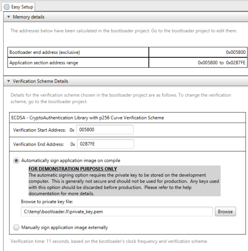
- Build Options Update
-
Since the generated hex file needs to be signed with the private key above, a post build step will have to be run. At this time a notification message shown below may be present.
This is providing the user information on how to enable post processing of the hex file, allowing it to be signed. For this step, the user needs to go to the Project->Properties and under Building, the user needs to enable the "Execute this line after build" and copy the line of code from the above message into the build step as shown below. This will cause the signing of the hex file to occur after each compile.
Figure 1-8. Adding Post Build Step for ECDSA Application 
1.3.6.1 Code Signing Options
Signing the Application Image
For the ECDSA verification method to work, the application image must be signed after compilation before the bootloader will allow the application to run. The Bootloader 16 MCC project gives two options for signing the code: Automatic signing on compile and manual signing.
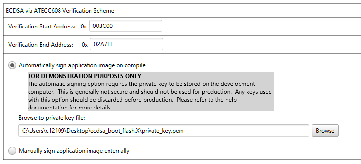
|
FOR DEMONSTRATION PURPOSES ONLY! |
Required Tools for Automatic Signing
When using the automatic signing option, the following tools must be installed on the development machine and added to the system PATH:
- OpenSSL - for more information about obtaining and installing OpenSSL, please refer to wiki.openssl.org/index.php/Binaries
- Python v3
Description
The default option is "Automatic signing on compile". This is the easiest option for demonstration purposes, but is not secure. Keys used with this signing method should not be used in production. The manual signing option should always be chosen for production.
Private keys should always be generated and stored in a Hardware Security Module (HSM) such that they are never available outside that hardware unit. The HSM should be used to sign production code. Interfacing with the HSM will be device specific and in more secure applications would be located in a secure room so this will require the manual signing flow. When getting started, however, it is easier to be able to automatically sign the image on compile and then move to secure keys for production. It is suggested that customers start with the automatic sign on compile option to develop their bootloader and application and then switch to the manually signing process for production. THE KEYS USED FOR THIS METHOD SHOULD BE DISCARDED AND NOT USED DURING PRODUCTION. The private key used to sign the code is what is securing the firmware update. Anyone with this key can create a malicious firmware update. It is generally recommended that this key is NOT available on developers machines for production keys. That machine could become compromised and the key could be taken. That developer could also intentionally leak that key. It is best limit access to that key as much as possible. If the key is generated in a HSM module in a secure room, access to that key can be limited, controlled, monitored and audited. This is the best option for a production key. For development, however, this type of restriction might be too cumbersome and thus the automatic signing on compile option is nice option FOR DEVELOPMENT PURPOSES ONLY.In the manual signing workflow, the application code is converted to a binary file automatically on compile. This binary file needs to be manually signed by the developer using their own signing process. The signature file needs to be provided to the "injectSignature.bat/.sh" script file. This script will read out the signature value from the signature file and inject it into the application header in the correct location. A proper signature is required before the bootloader will allow the application code to run.
This workflow is suggested for production so that the private keys can be secured in an appropriate Hardware Security Module (HSM). This workflow, however, can be difficult to setup at first. For demonstration and initial development, the automatic signing on compile option is suggested.1.3.6.1.1 Manual Signing: OpenSSL
When manual signing has been selected in the application project, it is the developers responsibility to generate the signature for the application image. Scripts are provided by MCC to assist, where possible, with this signing process. This section discusses how to manually sign an application image using OpenSSL.
NOTE: The process described below uses the private key directly during the signing process. This is STRONGLY DISCOURAGED in production as it gives the developer access to the private key directly. The private key should be protected from invalid usage and copying. This means, in general, some form of physical protection device, such as an HSM, to store the private key.
NOTE: Although software based keys are generally cheaper, this option is less secure compared to the HSM protection level. HSMs are physically protected from tampering without direct access while software based keys are stored on a hard drive or network, which is inherently at risk of compromise. As such, HSM keys are recommended when possible.
The steps described below can be used as a template to use any other signing method by replacing the signing step with the processes for your signing system.
Step 1: Required tools
sudo apt install opensslHexmate must be installed on your system path. This can be found in the under the mplabx_platform/bin folder in the MPLAB X IDE program files folder. This needs to be added to the system path.
Python v3 needs to be on your system and on the system path so the scripts are able to invoke it.
Step 2: Generating a key pair
The bootloader will need access to the public key that is used for the signature verification. This can come in the form of direct access to the public key file, or indirect access through a stored key in a secure element. Either way, the first step in the process is to generate a key pair. This step will depend on your signing system how this is done. For OpenSSL, we will be passing the private key directly on the command line so we are able to use the existing “Generate Key Pair Example” in the bootloader project.
For other signing systems, you may need to request a key pair to be generated and then request the system to export the public key file to give to the bootloader project.
Step 3: Modify the application project
In order to use a manual signing process, we need to configure the application project for manual signing. This is done in the ECDSA verification section by selecting the “Manually sign application image externally” option:
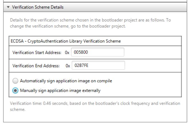
Once the manual signing option is selected, make sure to regenerate the application project using the “Generate” button in the MCC Project Resources pane. There are several tasks that are required to sign an application image:
- Filling in blank space inside the .hex file to complete the memory map
- Blank the signature location in the application header
- Shift the memory to address 0x0000 from whatever the shifted application reset vector is
- Convert the resulting .hex file to a binary (.bin) file
- Generate a signature certificate for the binary file
- Extract the signature value from the certificate
- Inject the signature value into the application header in the .hex file
When using the automatic signing workflow, the generated script does all of the above steps automatically on compile of the project.
When using the manual signing workflow, the post-build process must stop after step 4 since the signing step is a manual process. In this case, MCC generates two scripts. The postBuild.bat/.sh script that is run automatically on compile will run through steps 1-4 resulting in a binary image that is ready for signature generation. A second script is generated name injectSignature.bat/.sh that will then take a signature certificate file and inject it into the .hex file, covering steps 6 and 7. This script, however, must be run manually by the user and is described in a later section.
After the project has been generated, the final step to build an application image for signing is to compile the application project.
NOTE:When using MPLAB X 6.20 or later, it is important to make sure to do a production build. The clean/build button on the tool bar will not result in a .hex file being generated and thus the postBuild.bat/.sh file will be unable to generate the required binary file. To make a projection build, use the down arrow next to the build button and select “Clean and Build Main Project”.
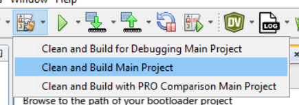
After compiling the project, there should be both a .hex file and a .bin file located in your projects /dist/<configuration>/production folder. The .bin file is the file that we want to generate a signature for.
Step 4: Generating the signature file using OpenSSL
This step generates a signature file for the application image using the pre-established private key. This step can be replaced with any other signing method of your choosing as long as the output of this step is a signature file in a .der/ASN.1 format or a binary file containing just the value of just the signature. This example uses OpenSSL to generate a signature file. Any other method can be used as long as it results in a valid signature generation.
OpenSSL uses the following command line to generate a signature file:
openssl dgst -sha<256/384> -sign <path_to_private_key> -out <path_to_output_signature_file> <path_to_binary_file_to_sign>In this example we are running this command from C:\example so all paths are from that reference point. We are signing an image in a project named app.X using the SHA256 algorithm. Note that the 16-bit Bootloader also supports SHA384. To sign the image, run the following command:
openssl dgst -sha256 -sign boot.X/private_key.pem -out app.X/dist/default/production/app.X.production.bin.signature.der app.X/dist/default/production/app.X.production.binThe above example will generate a certificate file with the required signature at app.X/dist/default/production/app.X.production.bin.signature.der.

NOTE - The specific naming convention and file location of the signature file above is an example. The signature file’s name and location can be chosen by the user, as long as the signature file is in a .der/ASN.1 format or binary file containing just the value of the signature.
If you want to verify the signature file is correct, you can run the following command:
openssl dgst -verify <path_to_public_key> -keyform PEM -sha<256/384> -signature <path_to_output_signature_file> -binary <path_to_binary_file_to_sign>So for this SHA256 example:
openssl dgst -verify boot.X/public_key.pem -keyform PEM -sha256 -signature app.X/dist/default/production/app.X.production.bin.signature.der -binary app.X/dist/default/production/app.X.production.binIf the signature file is correct, this should print "Verified OK" on the screen.
Step 5: Inject signature into application .hex file
If everything worked correctly in the step above, we should now have a certificate that contains the required signature for the application image. We need to extract that signature value from the certificate and inject it into the application image. As previously mentioned, this is all handled by the generated injectSignature.bat/.sh script.
NOTE - This step is written assuming the certificate is in a .der/ASN.1 format. For a binary formatted output you would need to comment out/remove the line in the below script that converts the .der/ASN.1 file to a binary file and then continue. This is true for OpenSSL but other signing mechanisms may not provide a full certificate file.
Inject the signature into the .hex file using the command below:
injectSignature.bat <absolute_path_to_compiler_bin_folder> <absolute_path_to_application_project> dist\default\production <hex_file_name> <path_to_output_signature_file>NOTE - The above command is executed from the /mcc_generated_files/boot folder rather than outside of the project folders where the OpenSSL command was run from. Please make sure to navigate to the correct folder that contains the scripts so that the scripts can find the required tools and files.
In the example where the files are located in C:\example, this results in:
injectSignature.bat "C:\Program Files\Microchip\xc16\v2.10\bin" C:\example\app.X dist\default\production app.X.production.hex ..\..\dist\default\production\app.X.production.bin.signature.derIf this script runs without any errors, then the .hex file of the application project has been modified to contain the value of the signature inside the .hex file and it is now ready to be loaded using the host application.
1.3.6.1.2 Manual Signing: Google HSM
When manual signing has been selected in the application project, it is the developer’s responsibility to generate the signature for the application image. Scripts are provided by MCC to assist, where possible, with this signing process. This section discusses how to manually sign an application image using Google Cloud HSM/KMS.
NOTE: The steps below outline how to perform the manual signing process using Google HSM, however there are many other HSM options available.
Step 1: Required tools
Google Cloud Project
To use Google Cloud HSM services, you’ll need to create a Google Cloud project. The steps to do so are outlined in the following Google Guide.
developers.google.com/workspace/guides/create-project
Google KMS Key Ring
Once you have a project created, you’ll need to create a Key Ring to store the signing key. For the following examples, we’ll assume we’ve created a Key Ring called “signing-demo-kr” with a location of “global”. This process is outlined in the following Google Guide.
cloud.google.com/kms/docs/create-key-ring
Google KMS Key
Within the Key Ring created above, you’ll need to create an asymmetric signing key. When prompted for Protection Level, select either “Software” or “HSM” depending on the level of protection desired.
NOTE: Although software based keys are generally cheaper, this option is less secure compared to the HSM protection level. HSMs are physically protected from tampering without direct access while software based keys are stored on a hard drive or network, which is inherently at risk of compromise. As such, HSM keys are recommended when possible.
Keep in mind that once a key is created, the protection level cannot be changed. When prompted for Purpose and Algorithm, select “Asymmetric sign” as the Purpose and “Elliptic Curve P-256 - SHA256 Digest” or “Elliptic Curve P-384 - SHA384 Digest” as the Algorithm. For the following examples, we’ll assume the key name is “signing-demo” with a version of “1” and “Elliptic Curve P-256 - SHA256 Digest” as the algorithm.NOTE: The scheduled key destruction date is automatically set as 30 days. To change this, navigate to “Additional settings” and select “Duration of ‘scheduled destruction’ state” during key creation. This process is further outlined in the following Google Guide.
cloud.google.com/kms/docs/create-key#create-asymmetric-sign
Google Cloud CLI
To export the public key and create the signature, Google Cloud CLI must be installed on your system. Instructions to do so are outlined in the following Google Guide.
cloud.google.com/sdk/docs/install
Once Google Cloud CLI is installed, you will need to add your Google Cloud account and project. The following Google Guide outlines the steps on how to complete setup.
cloud.google.com/sdk/docs/initializing
Hexmate
Hexmate must be installed on your system path. This can be found under the mplabx_platform/bin folder in the MPLAB X IDE program files folder. This needs to be added to the system path.
OpenSSL
OpenSSL executables must be installed on your system path. Please refer to the OpenSSL website for information about obtaining those executables for Windows or Mac OS X:
https://wiki.openssl.org/index.php/Binaries
sudo apt install opensslStep 2: Generating a key pair
gcloud kms keys versions get-public-key <key_version> --key=<key_name> --keyring=<key_ring_name> --location=<key_ring_location> --output-file=<public_key_output_location>gcloud kms keys versions get-public-key 1 --key=signing-demo --keyring=signing-demo-kr --location=global --output-file=C:\Users\example\MPLABXProjects\boot.X\public_key.pemMore details on exporting the public key with Google KMS can be found in the following Google Guide.
cloud.google.com/kms/docs/create-validate-signatures#validate_ec_signature
Step 3: Modify the application project
See Step 3 of Manual Signing: OpenSSL.
Step 4: Generating the signature file using Google Cloud KMS
This step generates a signature file for the application image using the pre-established private key.
gcloud kms asymmetric-sign --version=<key_version> --key=<key_name> --keyring=<key_ring_name> --location=<key_ring_location> --digest-algorithm=<digest_algorithm> --input-file=<file_to_sign> --signature-file=<signature_file>gcloud kms asymmetric-sign --version=1 --key=signing-demo --keyring=signing-demo-kr --location=global --digest-algorithm=sha256 --input-file=..\..\dist\default\production\app.X.production.bin --signature-file=..\..\dist\default\production\app.X.production.bin.signature.derThis will generate a certificate file with the required signature at app.X\dist\default\production\app.X.production.bin.signature.der
More details on creating a signature file with Google KMS can be found in the following Google Guide.
cloud.google.com/kms/docs/create-validate-signatures#create_signature
NOTE: The specific naming convention and file location of the signature file above is an example. The signature file’s name and location can be chosen by the user, as long as the signature file is in a .der/ASN.1 format or binary file containing just the value of the signature.
openssl dgst -sha<256/384> -verify <path_to_public_key> -signature <path_to_output_signature_file> -binary <path_to_binary_file_to_sign>openssl dgst -sha256 -verify C:\Users\example\MPLABXProjects\boot.X\public_key.pem -signature app.X\dist\default\production\app.X.production.bin.signature.der -binary app.X\dist\default\production\app.X.production.binIf the signature file is correct, this should print "Verified OK" on the screen.
More details on verifying the signature file with Google KMS can be found in the following Google Guide:
cloud.google.com/kms/docs/create-validate-signatures#validate_ec_signature
Step 5: Inject signature into the application .hex file
If everything worked correctly in the step above, we should now have a certificate that contains the required signature for the application image. We need to extract that signature value from the certificate and inject it into the application image. As previously mentioned, this is all handled by the generated injectSignature.bat/.sh script.
injectSignature.bat <absolute_path_to_compiler_bin_folder> <absolute_path_to_application_project> dist\default\production <hex_file_name> <path_to_output_signature_file>NOTE: The above command is executed from the <project_name>/mcc_generated_files/boot folder. Please make sure to navigate to the correct folder that contains the scripts so that the scripts can find the required tools and files.
injectSignature.bat "C:\Program Files\Microchip\xc16\v2.10\bin" C:\example\app.X dist\default\production app.X.production.hex ..\..\dist\default\production\app.X.production.bin.signature.derNOTE: If an error is received stating the hexmate command cannot be found, ensure Hexmate has been properly installed on your system path. This can be found under the mplabx_platform/bin folder in the MPLAB X IDE program files folder. Once it has been added to the path, close and reopen the terminal and re-run the command above.
If this script runs without any errors, then the .hex file of the application project has been modified to contain the value of the signature inside the .hex file and it is now ready to be loaded using the host application.
1.3.7 Application Header Details
- Extended Application Header Overview
-
At the beginning of each application binary is an Extended Application Header containing a variety of information about the application. The Extended Application Header has two basic sections. The first section contains the Application Header which contains just the basic information about the image.
-
The Checksum/CRC32/SHA256 or other signature of the application image used during verification.
-
The application Start and End addresses the code the signature checks.
-
A branch instruction that allows linking the bootloader code to the application
The second part of the Extended Application Header is the Application Details Header which contains other detailed information about the image such as version information of the image.
Application Header
The format of the Application Header is shown belowOffset
Length
Description
0
4
CRC32 of the image(Size of this field varies with verification method)
4
4
Start Address (inclusive - PC addresses)
8
4
End Address (inclusive - PC addresses)
12
4
Branch command to entry point of the Firmware Image
-
- Application Details Header
-
The second part of the Application Header is the Application Details Section. This section is designed to be expandable and allow the customer to add their own header types. In the current implementation, only two types of headers are defined. The first is the generic Application Details Header and the Application Version Header. These are defined below.
Start of Application Details Section Indicator – Header ID Value - 0
Offset
Length
Description
N
2
Start of Application Details Section Indicator ID (0x0000)
N+2
4
Start of Application Details Section Indicator Data Length (2 - always 2 bytes)
N+6
4
Count of Application Details in the section (Includes this one)
- Application Version Number Header
-
The second Application Details header is the Application Version Number header. This header provides a place for the version number of this application image and is defined below
Application Version Number Header - ID Value - 2
Offset
Length
Description
N
2
Version Number Header ID (0x0002)
N+2
4
Version Number Data Length (4)
N+6
4
Version Number in format of 0x00:major:minor:patch each major/minor/patch will be 0-255 limited.
- CRC32 Extended Application Header Example
-
A detailed example of a complete Application header is shown below. The verification types is CRC32 which computes a 32 bit CRC of the image within the space give. The details are shown below.
The below examples go through the and example CRC32 header.
-
The application CRC32 is 0x24E3_722A
-
The application image starts at 0x0000_1C00
-
The application image ends at 0x0002_A7FE
-
The application version number is 0x010203
Offset
Length
Description
0
4
CRC32 0x24E3_722A
4
4
0x0000_1C00
8
4
0x0002_A7FE
12
4
Branch command to entry point of the Firmware Image
16
2
Start of Application Details Section Indicator ID (0x0000)
18
4
Start of Application Details Section Indicator Data Length (2 - always 2 bytes)
22
4
Count of Application Details in the section (2 In this example. Includes this one)
26
2
Version Number Header ID (0x0002)
28
4
Version Number Data Length (4)
32
4
Version Number in format of 0x00:major:minor:patch (0x010203).
-
1.3.7.1 Adding Application Header Fields Example
Often the user will want to add more fields to the application header the bootloader can check during start up. With this bootloader, any number of Application Headers can be added to the Application Details section. The Application Header consists of a list of linked 3 entry structures containing the ID, Length and Data. Any number of these 3 entry structures can be added provided they meet the following requirements:
- Each Application Header ID must be unique and be greater than 2
- The Application Header Length, which is the length of the data field in bytes, must be even
- The Actual Data field must also be an even number of bytes in length
- The Count in the Application Details Section Indicator at the beginning of the header list should reflect the total number of application header plus 1.
The changes to the bootloader code to support these fields are described in the Bootloader:Bootloader help documentation in the verfication section.
New Example Fields
For this example, three new application header fields will be added to the existing header which just contains the version number. The three new fields are:
- A Customer 16-bit (2 Byte) field
- A Customer 32-bit (4 Byte) field
- A Customer 12-Byte string field
Below is an example of a modified version of a CRC32 Extend Application Header with three added fields:
-
The application CRC32 is 0x24E3_722A
-
The application image starts at 0x0000_1C00
-
The application image ends at 0x0002_A7FE
-
The application version number is 0x010203
-
Customer 16-Bit Value containing 0x4243
-
Customer 32-Bit Value containing 0x31415965
-
Customer 12 Character string (“Mar 12 2023”) – 12 bits including Null terminator
CRC32 Extended Application Header Example with Custom Fields
|
Offset |
Length |
Value |
Description |
|---|---|---|---|
|
0 |
4 | 0x24E3_722A |
CRC32 0x24E3_722A |
|
4 |
4 | 0x0000_1C00 |
Application Start Address for CRC calculation (0x0000_1C00) |
|
8 |
4 | 0x0002_A7FE |
Application End Address for CRC calculation (0x0002_A7FE) |
|
12 |
4 |
Branch command to entry point of the Firmware Image | |
|
16 |
2 | 0x0000 |
Start of Application Details Section Indicator ID (Always 0x0000) |
|
18 |
4 | 0x0002 |
Start of Application Details Section Indicator Data Length (2 - always 2 bytes) |
|
22 |
4 |
0x0005 |
Count of Application Details in the section (5 In this example. Includes this one) |
|
26 |
2 |
0x2 |
Version Number Header ID (0x0002) |
|
28 |
4 |
0x0004 |
Version Number Data Length (4) |
|
32 |
4 |
0x00010203 |
Version Number in format of 0x00:major:minor:patch (0x010203). |
|
New Fields below | |||
|
36 |
2 |
0x0003 |
Customer 16 Bit Number Header ID (0x0003) |
|
38 |
4 |
0x02 |
Customer 16 Bit Number Data Length (2) |
|
42 |
2 |
0x4243 |
Customer 16 Bit Number (0x4243) |
|
44 |
2 |
0x04 |
Customer 32 Bit Number Header ID (0x0004) |
|
46 |
4 | 0x0002 |
Customer 32 Bit Number Data Length (4) |
|
50 |
4 | 0x31415965 |
Customer 32 Bit Number (0x31415965) |
|
54 |
2 | 0x0003 |
Customer String Header ID (0x0005) |
|
56 |
4 | 0x000C |
Customer String Header Length (12) |
| 60 |
12 | Mar 12 2023 |
Customer String (“Mar 12 2023”) – 12 bits including Null terminator |
1.4 Compiler and Linker Options
Compiler, Linker and Post Build Options
Since the bootloader often requires specialized build features, extra build options are often required. These settings are automatically enabled in the most recent version and are documented here in case the user has questions.
- Code Protect / Code Guard settings
-
When the user selected code protect, the device is configured to use Codeguard. This feature requires special linker options to place the code in the correct place. Below are the linker settings for both the bootloader and applications.
Bootloader Linker Settings
–add-flags-code=boot,–add-flags-const=boot,-D__USE_BFA
The steps needed to change this are shown below.-
Goto Project Properties
-
Goto XC16->xc16-ld/XC-DSC->xc-dsc-ld
-
Under additional options add the following: –add-flags-code=boot,–add-flags-const=boot,-D__USE_BFA
-
- ECDSA Verification with Code Protect / Code Guard settings
-
When the user selected code protect, the device is configured to use Codeguard. This feature requires special linker options to place the code in the correct place. Below are the linker settings for both the bootloader and applications.
Bootloader Linker Settings
–add-flags-code=boot,–add-flags-const=boot,-D__USE_BFA
The steps needed to change this are shown below.-
Goto Project Properties
-
Goto XC16->xc16-ld/XC-DSC->xc-dsc-ld
-
Under additional options add the following: –add-flags-code=boot,–add-flags-const=boot,-D__USE_BFA
Application Post Build Settings
As the final part of the build process, the application code needs to be signed and converted to a hex format to download. The following command needs to be added to the Post Build process.
Windows Post Build Command
cd mcc_generated_files/boot && postBuild.bat $(MP_CC_DIR) $(ProjectDir) $(ImageDir) $(ImageName) $(IsDebug)
Linux Post Build Command
cd mcc_generated_files/boot && ./postBuild.sh $(MP_CC_DIR) $(ProjectDir) $(ImageDir) $(ImageName) $(IsDebug)
-
Goto Project Properties
-
Select the 'Building' left navigation node.
-
Check the box next to 'Execute this line after the build'.
-
- Application Side Linker Workaround
-
Due to XC16-2324 and XC16-2333, it is possible for link-time or run-time issues in specific situations when using this bootloader solution. The following workarounds are required on the application side only when the project has the all of the following settings:
- Device > 64KB
- Code Protect / Code Guard enabled
- XC-16 (any version) or XC-DSC 3.00
Workaround #1 (Recommended): Update to XC-DSC 3.10 or newer. It is recommended to update to the latest compiler when possible.
Workaround #2: When it is not possible to update the version of the compiler in use for the project, the following manual workaround will resolve this potential issue.- Copy the device linker file into the project. The location of
the golden linker file on the system depends on the compiler
versions and Device Family Packs (DFPs) installed. The easiest
way to find the most current linker file is to first build the
project with the default settings. At the very end of the build
process in the Output window, there will be a line that shows
the linker file used for the build as show below. Copy this
linker file and place in the root of the project folder.
- "Info: Loading file: <FILE PATH>/gld/<device_name>.gld”
- Modify the linker
file. Open the copied version of the linker file in a text/code
editor. Locate the first SECTIONS declaration and add the
following line inside of the SECTIONS{} declaration at the top.
.application_header 0x<BOOT_CONFIG_APPLICATION_IMAGE_APPLICATION_HEADER_ADDRESS>: { KEEP(*(.application_header)); } >programNOTE: Replace BOOT_CONFIG_APPLICATION_IMAGE_APPLICATION_HEADER_ADDRESS with the resolved value defined in boot_config.h. These instructions and the exact line to copy with the resolved value already injected can be found in application_header.S in 16-bit Bootloader version 1.25.1 and later.
When complete, it should look similar to the following:
Save the modified linker file.SECTIONS { .application_header 0x<BOOT_CONFIG_APPLICATION_IMAGE_APPLICATION_HEADER_ADDRESS>: { KEEP(*(.application_header)); } >program #if !defined(__CORESIDENT) || defined(__DEFINE_RESET) .reset : { SHORT(ABSOLUTE(__reset)); SHORT(0x04); SHORT((ABSOLUTE(__reset) >> 16) & 0x7F); SHORT(0); } >reset #endif - Add the modified linker file to the project. In the "Projects" pane in MPLAB X, right click on the "Linker Files" folder. Select "Add Existing Item" Browse to the modified linker file modified in step 2.
1.5 Merging Bootloader and Application Hex Files For Production
When going to production it is often beneficial to merge the bootloader with the initial application code. This allows the factory to program just a single hex file and also allows the user to have an operating device out of the box that they can update with the latest application code.
During the Application Project creation process MCC generated two scripts that can be used to merge the bootloader and application hex files into a single hex file. This single hex file can then be used to program the device in the factory thereby removing the extra step of downloading and programming the application separately. The two scripts generated are listed below. One is for a windows system and one for a linux system.
-
"/IOT_APP.X/mcc_generated_files/boot/combineAppAndBootloaderHex.bat" if you are on a Windows machine.
-
"/IOT_APP.X/mcc_generated_files/boot/combineAppAndBootloaderHex.sh" if you are on a Linux/Unix/Mac machine.
These scripts use the config bits from the application so it's imperative that the user has matched the application and bootloader configuration bits in their project. Also if the user is using codeguard and wants to write protect the device, they need to set the write protect bits in the application project and then merge the files.
1.6 Building for Production


-
Select the dropdown next to the 'Build' or 'Clean and Build' button and select 'Build Main Project' or 'Clean and Build Main Project' respectively


-
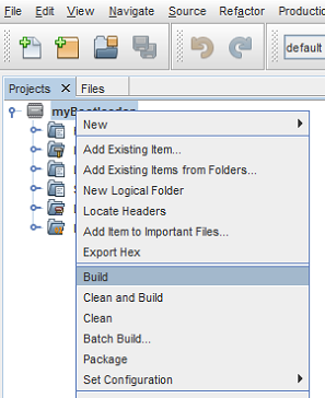
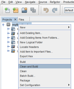
Right click on the project name in the Projects window and select 'Build' or 'Clean and Build'
