
1.19 PWM Generation
This example shows how to use the PWM peripheral to generate 3-phase PWM signals with dead time.
Description
This example shows how to configure the PWM to generate synchronous 3-phase PWM signals with dead time (used for motor control). The duty cycle of the PWM is updated in the interrupt handler.
Downloading and Building the Application
To clone or download this application from Github, go to the main page of this repository and then click Clone button to clone this repository or download as zip file. This content can also be downloaded using content manager by following these instructions.
Path of the application within the repository is apps/pwm/pwm_synchronous_channels/firmware.
To build the application, refer to the following table and open the project using its IDE.
| Project Name | Description |
|---|---|
| sam_a7g5_ek.X | MPLABX project for SAMA7G54 Evaluation Kit |
Setting Up AT91Bootstrap Loader
To load the application binary onto the target device, we need to use at91bootstrap loader. Refer to the at91bootstrap loader documentation for details on how to configure, build and run bootstrap loader project and use it to bootstrap the application binaries.
Setting Up the Hardware
The following table shows the target hardware for the application projects.
| Project Name | Description |
|---|---|
| sam_a7g5_ek.X | SAMA7G54 Evaluation Kit |
Setting Up SAMA7G5 Evaluation Kit
- Connect the Debug USB port on the board to the computer using a micro USB cable
Running the Application
- Build and Program the application using their respective IDEs
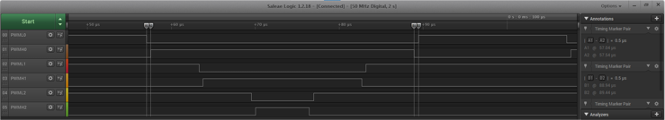
- Observe the high-side and low-side PWM waveforms on the oscilloscope
- Observe the dead time between the
high side and low side
| PWM Channel | SAMA7G5 Evaluation Kit |
|---|---|
| CH0_PWML | PE02 (Pin 32 of RPi connector(J13)) |
| CH0_PWMH | PE03 (Pin 38 of RPi connector(J13)) |
| CH1_PWML | PE04 (Pin 35 of RPi connector(J13)) |
| CH1_PWMH | PE05 (Pin 40 of RPi connector(J13)) |
| CH2_PWML | PE06 (Pin 12 of RPi connector(J13)) |
| CH2_PWMH | PE07 (Pin 11 of RPi connector(J13)) |