The timer can be configured to measure the pulse width of the ERS signal as per the settings shown in Table 2-5.
| Timer Setting | Value |
|---|---|
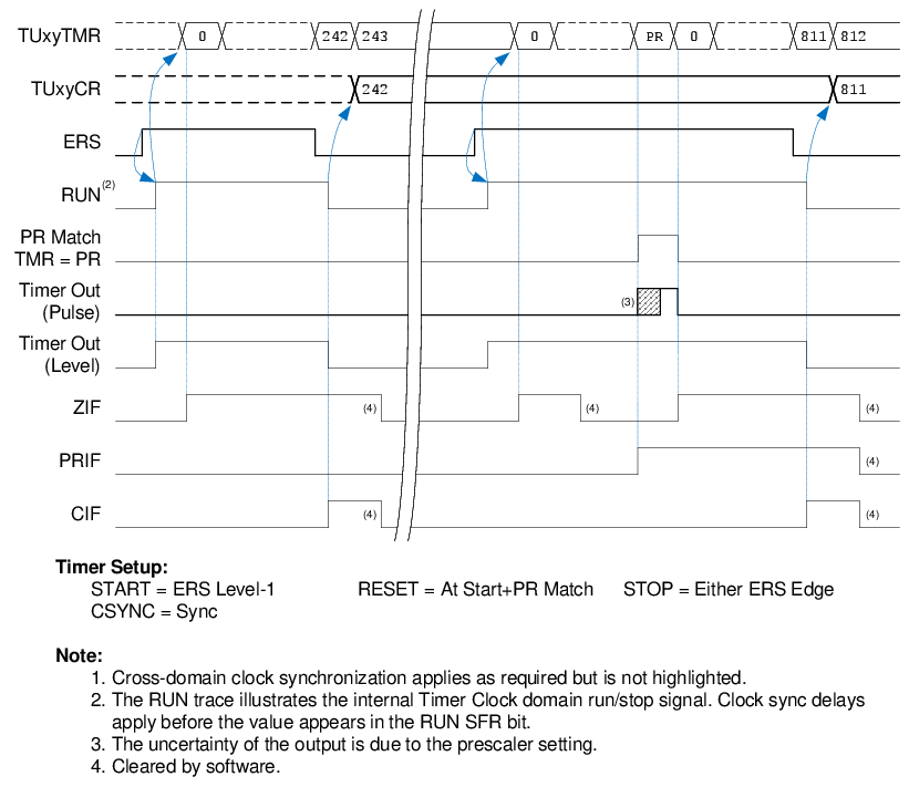
| START | ERS Level-1 |
| RESET | At Start + PR Match |
| STOP | Either ERS Edge |
| CSYNC (Clock Sync) | Sync |
| EPOL (ERS Polarity) |
True Level (to measure “high” pulse width) Inverted Level (to measure “low” pulse width) |
| OSEN (One-shot) |
True Level (to start at rising ERS edge) Inverted Level (to start at falling ERS edge) |
| PR (Period Register) | Desired Period Value |
When the ERS input rises (changes from 0 to 1), the
counter resets to zero and begins counting. When the counter resets to zero, ZIF
interrupt occurs. At the following falling edge of ERS, the counter value is captured
into the TUxyCR capture register, the counter stops, and CIF interrupt occurs. The
captured value in the TUxyCR register is the ‘high’ pulse-width time. This is shown in
Figure 2-7. To measure the
‘low’ pulse-width time, invert the ERS polarity by setting the EPOL bit.
The software must read the captured value before the completion of the next pulse. The One-Shot mode can be used to disable the subsequent start edge, allowing more time for the software to read the captured value.
1 to measure ‘low’
time). The PRIF interrupt occurs only if the idle time exceeds the PR value.
Alternatively, this can also be measured using the use case in Input Stuck High/Low.