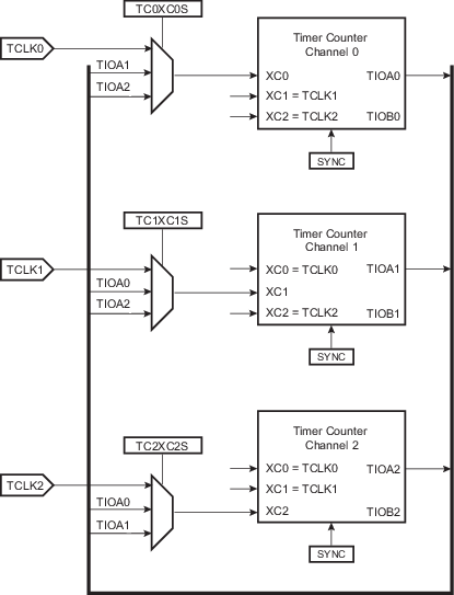
At block level, input clock signals of each channel can be connected either to the external inputs TCLKx, or to the internal I/O signals TIOAx for chaining(1) by programming the Block Mode register (TC_BMR). See Clock Chaining Selection.
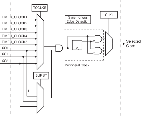
Each channel can independently select an internal or external clock source for its counter(2):
- External clock signals: XC0, XC1 or XC2
- Internal clock signals: PCK6 or PCK7 (TC0 only), MCK/8, MCK/32, MCK/128, SLCK
This selection is made by the TCCLKS bits in the Channel Mode register (TC_CMRx).
The selected clock can be inverted with TC_CMRx.CLKI. This allows counting on the opposite edges of the clock.
The burst function allows the clock to be validated when an external signal is high. The BURST parameter in the TC_CMRx defines this signal (none, XC0, XC1, XC2). See Clock Selection.
- 1.In Waveform mode, to chain two
timers, it is mandatory to initialize some parameters:
- Configure TIOx outputs to 1 or 0 by writing the required value to TC_CMRx.ASWTRG.
- Bit TC_BCR.SYNC must be written to 1 to start the channels at the same time.
- 2.In all cases, if an external clock or asynchronous internal clock PCK6 or PCK7 (TC0 only) is used, the duration of each of its levels must be longer than the peripheral clock period, so the clock frequency will be at least 2.5 times lower than the peripheral clock.