Figure 1. Input Channel Model
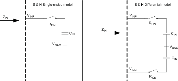
where:
- ZIN is input impedance in Single-ended or Differential mode
- CIN = 2 to 8 pF ±20% depending on the gain value and mode (SE or DIFF); temperature dependency is negligible
- RON is typical 2 kΩ and 8 kΩ max (worst case process and high temperature)
The following formula is used to calculate input impedance:
where:
- fS is the sampling frequency of the AFE channel
- Typ values are used to compute AFE input impedance ZIN
Table 1. Input Capacitance (CIN) Values Gain Selection Single-ended Differential Unit 1 2 2 pF 2 4 4 4 8 8 Table 2. ZIN Input Impedance fS (MHz) 1 0.5 0.25 0.125 0.0625 0.03125 0.015625 0.007813 CIN = 2 pF ZIN (MΩ) 0.5 1 2 4 8 16 32 64 CIN = 4 pF ZIN (MΩ) 0.25 0.5 1 2 4 8 16 32 CIN = 8 pF ZIN (MΩ) 0.125 0.25 0.5 1 2 4 8 16