In the figures below, the MOSI line shifting edge is represented with a hold time equal to 0. However, it is important to note that for this device, the MISO line is sampled prior to the MOSI line shifting edge. As shown further below, the device sampling point extends the propagation delay (tp) for slave and routing delays to more than half the SPI clock period, whereas the common sampling point allows only less than half the SPI clock period.
As an example, an SPI Slave working in Mode 0 can be safely driven if the SPI Master is configured in Mode 0.
Figure 1. MISO Capture in Master Mode
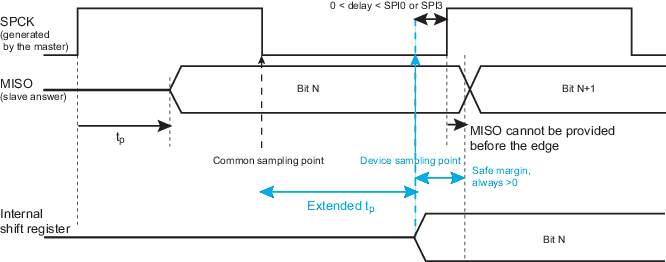
Figure 2. SPI Master Mode with (CPOL= NCPHA = 0) or (CPOL= NCPHA=
1)
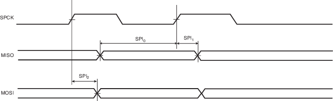
Figure 3. SPI Master Mode with (CPOL = 0 and NCPHA=1) or (CPOL=1 and
NCPHA= 0)
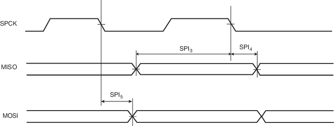
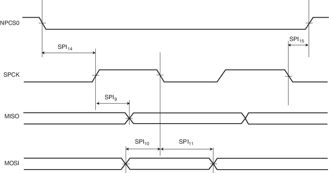
Figure 4. SPI Slave Mode with (CPOL=0 and NCPHA=1) or (CPOL=1 and
NCPHA=0)
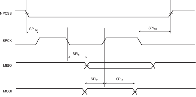
Figure 5. SPI Slave Mode with (CPOL = NCPHA = 0) or (CPOL= NCPHA=
1)