Hardware Configuration
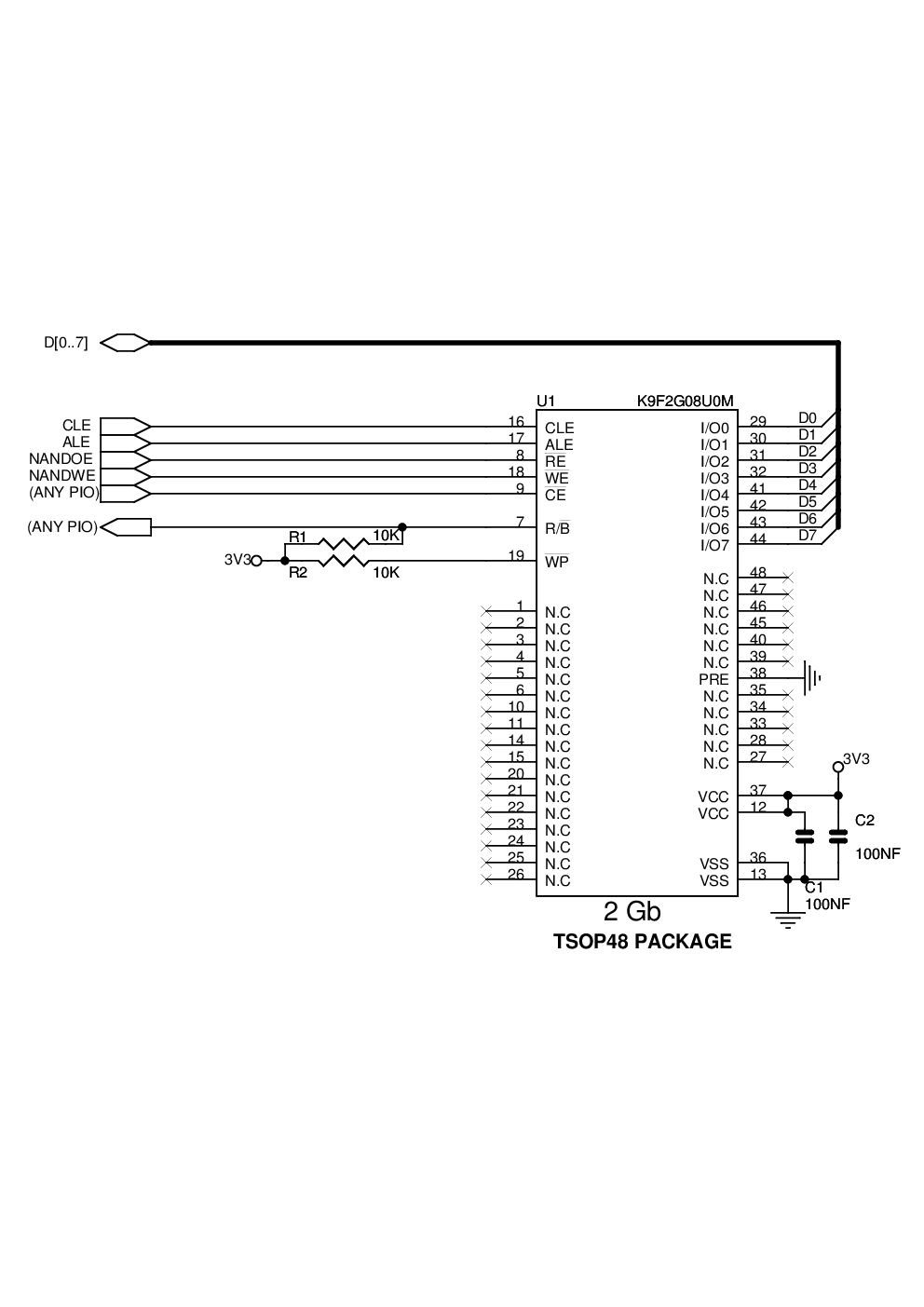
Figure 1. 8-bit NAND Flash
Software Configuration
Perform the following configuration:
- 1.Select the chip select used to drive the NAND Flash by setting the bit CCFG_SMCNFCS.SMC_NFCSx.
- 2.Reserve A21 / A22 for ALE / CLE functions. Address and Command Latches are controlled by setting the address bits A21 and A22, respectively, during accesses.
- 3.NANDOE and NANDWE signals are multiplexed with PIO lines. Thus, the dedicated PIOs must be programmed in Peripheral mode in the PIO controller.
- 4.Configure a PIO line as an input to manage the Ready/Busy signal.
- 5.Configure SMC CS3 Setup, Pulse, Cycle and Mode according to NAND Flash timings, the data bus width and the system bus frequency.
In this example, the NAND Flash is not addressed as a “CE don’t care”. To address it as a “CE don’t care”, connect NCS3 (if SMC_NFCS3 is set) to the NAND Flash CE.