In cases where certain interfaces are not used, the associated pins need to be configured properly. For example, the pins of an unused crystal oscillator can be left floating (DNC) and must not be grounded. If a PLL is not used or bypassed, and only the divider circuitry is used, then the PLL’s pins can be powered without RC filter circuitry.
For SmartFusion2/IGLOO2 devices with multiple SerDes blocks, designers should tie off unused SerDes blocks, as shown in the following figure.
For banks configured as LPDDR or single-ended I/O (and MDDR or FDDR functionalities are not being used), VREFx can be left floating (DNC) even though the corresponding bank supply is still powered.
To allow a SmartFusion2/IGLOO2 device, to exit from reset, some of the bank supplies (VDDIx) must always be powered, even if associated bank I/Os are unused (as shown in Table 3 and Table 2).
For details on bank locations for all the devices, see DS0115: SmartFusion2 Pin Descriptions Datasheet or DS0124: IGLOO2 Pin Descriptions Datasheet.
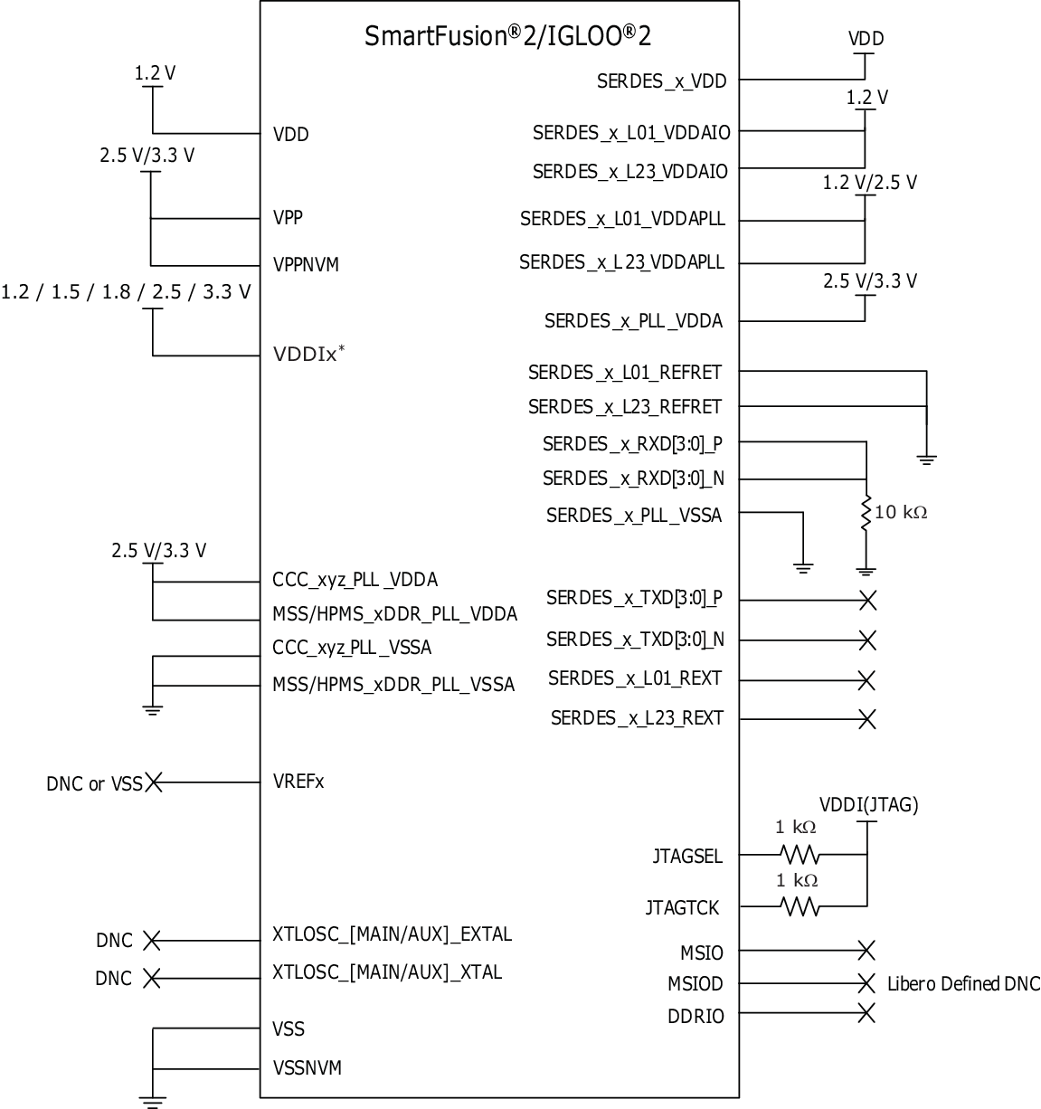
- 1.For M2S090T(S), M2GL090T(S), M2S150T(S), and M2GL150T(S) devices, the VPP and VPPNVM must be connected to a 3.3 V supply.
- 2.SERDES_RXD pin connections are changed to VSS through a 10 kΩ resistor to reduce the latch-up risk. This change does not affect the old board design functionality.
- 3.*There are some exceptions. For recommendations on unused VDDI supplies, see the following tables. The SmartFusion2/IGLOO2 devices have multiple bank supplies. In cases where specific banks are not used, connect them as listed in the following tables. If there is no recommendation provided for a device-bank supply combination, it means that the bank is not pinned out.
|
Bank Supply Names |
FC1152 |
FG896 |
FG676 |
|
FCS536 |
FCV484 |
|---|---|---|---|---|---|---|
|
M2S150T/ M2GL050T |
M2S050T/ M2GL050T |
M2S090T/ M2GL090T |
M2S060T/ M2GL060T |
M2S150T/ M2GL150T |
M2S150T/ M2GL150 |
|
|
VDDI0 |
— |
Connect to VSS through a 10 kΩ resistor |
— |
— |
||
|
VDDI1 |
Connect to VSS through a 10 kΩ resistor |
Must connect to VDDI1 |
Connect to VSS through a 10 kΩ resistor.
|
|||
|
VDDI2 |
Connect to VSS through a 10 kΩ resistor |
Must connect to VDDI2 |
Must connect to VDDI2 |
Must connect to VDDI2 |
Connect to VSS through a 10 kΩ resistor | |
|
VDDI3 |
Connect to VSS through a 10 kΩ resistor |
Must connect to VDDI3 |
Must connect to VDDI3 |
Must connect to VDDI3 |
Connect to VSS through a 10 kΩ resistor | |
|
VDDI4 |
Connect to VSS through a 10 kΩ resistor |
— |
Must connect to VDDI4 |
Connect to VSS through a 10 kΩ resistor |
||
|
VDDI5 |
Connect to VSS through a 10 kΩ resistor |
|||||
|
VDDI6 |
Must connect to VDDI6 |
Connect to VSS through a 10 kΩ resistor |
Must connect to VDDI6 |
Must connect to VDDI6 |
||
|
VDDI7 |
Must connect to VDDI7 |
Connect to VSS through a 10 kΩ resistor |
Must connect to VDDI7 |
Must connect to VDDI7 |
||
|
VDDI8 |
Connect to VSS through a 10 kΩ resistor |
|||||
|
VDDI9 |
Connect to VSS through a 10 kΩ resistor |
— |
Connect to VSS through a 10 kΩ resistor |
|||
|
VDDI10 |
Connect to VSS through a 10 kΩ resistor |
— |
— |
— |
Connect to VSS through a 10 kΩ resistor |
|
|
VDDI11 |
Connect to VSS through a 10 kΩ resistor |
— |
— |
— |
Connect to VSS through a 10 kΩ resistor |
|
|
VDDI12 |
Connect to VSS through a 10 kΩ resistor |
— |
— |
— |
Connect to VSS through a 10 kΩ resistor |
|
|
VDDI13 |
Connect to VSS through a 10 kΩ resistor |
— |
— |
— |
Connect to VSS through a 10 kΩ resistor |
|
|
VDDI14 |
Connect to VSS through a 10 kΩ resistor |
— |
— |
— |
Connect to VSS through a 10 kΩ resistor |
|
|
VDDI15 |
Connect to VSS through a 10 kΩ resistor |
— |
— |
— |
Connect to VSS through a 10 kΩ resistor |
|
|
VDDI16 |
Connect to VSS through a 10 kΩ resistor |
— |
— |
— |
Connect to VSS through a 10 kΩ resistor |
|
|
VDDI17 |
Connect to VSS through a 10 kΩ resistor |
— |
— |
— |
Connect to VSS through a 10 kΩ resistor |
|
|
VDDI18 |
Connect to VSS through a 10 kΩ resistor |
— |
— |
— |
Connect to VSS through a 10 kΩ resistor |
— |
- 1.The unused VDDI# pins must be connected to VSS through a 10 KΩ resistor. The VDDI# pins can be grouped and connected to one 10 KΩ resistor or a 10 KΩ resistor can be used for each VDDI# bank, it completely depends on the board layout. In the earlier version of the document, the unused VDDI# pins were recommended to be configured as DNC, and this cannot create functionality issue. Microchip recommends connecting to Ground through a 10 KΩ resistor to improve the board reliability.
|
Bank Supply Names |
FG484 |
|||||
|---|---|---|---|---|---|---|
|
M2S090T/ M2GL090T |
M2S060T/ M2GL060T |
M2S050T/ M2GL050T |
M2S025T/ M2GL025T |
M2S010T/ M2GL010T |
M2S005/ M2GL005 |
|
|
VDDI0 |
— |
— |
Connect to VSS through a 10 kΩ resistor |
|||
|
VDDI1 |
Connect to VSS through a 10 kΩ resistor |
Must connect to VDDI1 |
Must connect to VDDI1 |
Must connect to VDDI1 |
Must connect to VDDI1 |
|
|
VDDI2 |
Must connect to VDDI2 |
Must connect to VDDI2 |
— |
Must connect to VDDI2 |
Must connect to VDDI2 |
Must connect to VDDI2 |
|
VDDI3 |
Must connect to VDDI3 |
— |
Must connect to VDDI3 |
Connect to VSS through a 10 kΩ resistor |
Must connect to VDDI3 |
Connect to VSS through a 10 kΩ resistor |
|
VDDI4 |
Connect to VSS through a 10 kΩ resistor |
Must connect to VDDI4 |
Connect to VSS through a 10 kΩ resistor |
Must connect to VDDI4 |
Connect to VSS through a 10 kΩ resistor |
Must connect to VDDI4 |
|
VDDI5 |
Connect to VSS through a 10 kΩ resistor |
|||||
|
VDDI6 |
Connect to VSS through a 10 kΩ resistor |
|||||
|
VDDI7 |
Connect to VSS through a 10 kΩ resistor |
— |
||||
|
VDDI8 |
Connect to VSS through a 10 kΩ resistor |
— |
— |
— |
||
|
VDDI9 |
— |
Connect to VSS through a 10 kΩ resistor |
— |
— |
— |
— |
- 1.The unused VDDI# pins must be connected to VSS through a 10 KΩ resistor. The VDDI# pins can be grouped and connected to one 10 KΩ resistor or a 10 KΩ resistor can be used for each VDDI# bank, it completely depends on the board layout. In the earlier version of the document, the unused VDDI# pins were recommended to be configured as DNC, and this cannot create functionality issue. Microchip recommends connecting to Ground through a 10 KΩ resistor to improve the board reliability.
|
Bank Supply Names |
VF400 |
FCS325 |
|||||||
|---|---|---|---|---|---|---|---|---|---|
|
M2S060T/ M2GL060T |
M2S050T/ M2GL050T |
M2S025T/ M2GL025T |
M2S010T/ M2GL010T |
M2S005/ M2GL005 |
M2S090T/ M2GL090T |
M2S060T/ M2GL060T |
M2S050T/ M2GL050T |
M2S025T/ M2GL025T |
|
|
VDDI0 |
— |
Connect to VSS through a 10 kΩ resistor |
— |
— |
Connect to VSS through a 10 kΩ resistor |
||||
|
VDDI1 |
Connect to VSS through a 10 kΩ resistor |
Must connect to VDDI1 |
Must connect to VDDI1 |
Must connect to VDDI1 |
Must connect to VDDI1 |
Connect to VSS through a 10 kΩ resistor
|
Must connect to VDDI1 |
Must connect to VDDI1 |
|
|
VDDI2 |
Must connect to VDDI2 |
— |
Must connect to VDDI2 |
Must connect to VDDI2 |
Must connect to VDDI2 |
Must connect to VDDI2 |
Must connect to VDDI2 |
Must connect to VDDI2 |
— |
|
VDDI3 |
— |
Must connect to VDDI3 |
Connect to VSS through a 10 kΩ resistor |
Must connect to VDDI3 |
Must connect to VDDI3 |
Must connect to VDDI3 |
Connect to VSS through a 10 kΩ resistor |
||
|
VDDI4 |
Must connect to VDDI4 |
Connect to VSS through a 10 kΩ resistor |
Must connect to VDDI4 |
Connect to VSS through a 10 kΩ resistor |
Must connect to VDDI4 |
Connect to VSS through a 10 kΩ resistor |
Must connect to VDDI4 |
||
|
VDDI5 |
Connect to VSS through a 10 kΩ resistor |
||||||||
|
VDDI6 |
Connect to VSS through a 10 kΩ resistor |
||||||||
|
VDDI7 |
Connect to VSS through a 10 kΩ resistor |
— |
Connect to VSS through a 10 kΩ resistor |
||||||
|
VDDI8 |
Connect to VSS through a 10 kΩ resistor |
— |
— |
— |
Connect to VSS through a 10 kΩ resistor |
||||
|
VDDI9 |
Connect to VSS through a 10 kΩ resistor |
— |
— |
— |
— |
— |
Connect to VSS through a 10 kΩ resistor |
— |
— |
- 1.The unused VDDI# pins must be connected to VSS through a 10 KΩ resistor. The VDDI# pins can be grouped and connected to one 10 KΩ resistor or a 10 KΩ resistor can be used for each VDDI# bank, it completely depends on the board layout. In the earlier version of the document, the unused VDDI# pins were recommended to be configured as DNC, and this cannot create functionality issue. Microchip recommends connecting to Ground through a 10 KΩ resistor to improve the board reliability.
|
Bank Supply Names |
VF256 |
TQ144 |
|||
|---|---|---|---|---|---|
|
M2S025T/ M2GL025T |
M2S010T/ M2GL010T |
M2S005S/ M2GL005S |
M2S010S/ M2GL010S |
M2S005S/ M2GL005S |
|
|
VDDI0 |
Connect to VSS through a 10 kΩ resistor |
||||
|
VDDI1 |
Must connect to VDDI1 |
Must connect to VDDI1 |
Must connect to VDDI1 |
— |
— |
|
VDDI2 |
Must connect to VDDI2 |
Must connect to VDDI2 |
Must connect to VDDI2 |
Must connect to VDDI2 |
Must connect to VDDI2 |
|
VDDI3 |
Connect to VSS through a 10 kΩ resistor |
||||
|
VDDI4 |
Must connect to VDDI4 |
Must connect to VDDI4 |
Must connect to VDDI4 |
Must connect to VDDI4 |
Must connect to VDDI4 |
|
VDDI5 |
Connect to VSS through a 10 kΩ resistor |
— |
Connect to VSS through a 10 kΩ resistor |
||
|
VDDI6 |
Connect to VSS through a 10 kΩ resistor |
||||
|
VDDI7 |
Connect to VSS through a 10 kΩ resistor |
— |
Connect to VSS through a 10 kΩ resistor |
— |
|
- 1.The unused VDDI# pins must be connected to VSS through a 10 KΩ resistor. The VDDI# pins can be grouped and connected to one 10 KΩ resistor or a 10 KΩ resistor can be used for each VDDI# bank, it completely depends on the board layout. In the earlier version of the document, the unused VDDI# pins were recommended to be configured as DNC, and this cannot create functionality issue. Microchip recommends connecting to Ground through a 10 KΩ resistor to improve the board reliability.